Hydraulic oil tank with anti-corrosion and high-temperature-resistant functions

A hydraulic oil tank, high temperature resistant technology, applied in the direction of oil supply tank device, fluid pressure actuating device, fluid pressure actuating system components, etc. problems such as poor effect, to achieve the effect of fast heat dissipation, simple structure, and accelerated heat dissipation

Pending Publication Date: 2022-07-01
上海钦滨新材料科技有限公司
View PDF0 Cites 0 Cited by
  • Summary
  • Abstract
  • Description
  • Claims
  • Application Information

AI Technical Summary

Problems solved by technology

[0003] The structure of the existing fuel tank is as follows: including the fuel tank, a partition can be arranged in the fuel tank, and the partition divides the fuel tank into a cold oil area and a hot oil area, and the existing oil tank usually has the following disadvantages: the cold oil area and the hot oil area There is no suitable channel between the zones, and the high-temperature hy

Method used


Image

  • Hydraulic oil tank with anti-corrosion and high-temperature-resistant functions
  • Hydraulic oil tank with anti-corrosion and high-temperature-resistant functions
  • Hydraulic oil tank with anti-corrosion and high-temperature-resistant functions

Examples


Embodiment 1

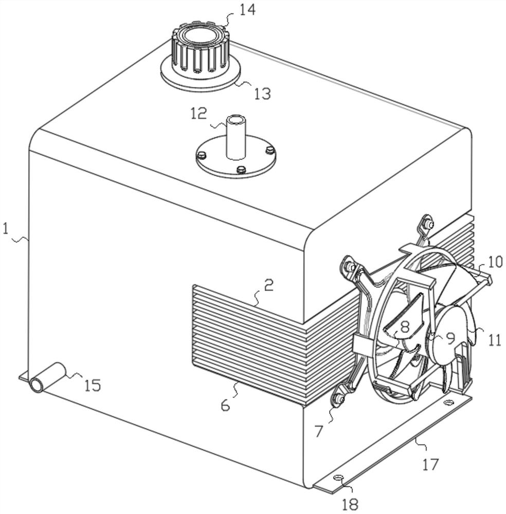
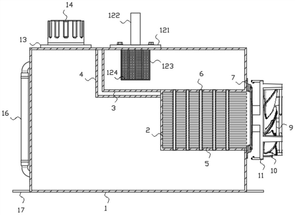
[0019] see Figure 1-3 , the present invention provides a technical solution: a hydraulic oil tank with anti-corrosion and high-temperature resistance, comprising a tank body 1, the tank body is made of composite materials, and has absolute sealing performance, anti-corrosion performance and high temperature resistance performance, thereby effectively improving the hydraulic pressure. The service life of the fuel tank, the fuel tank body 1 is provided with a mounting groove 2 on one side, the fuel tank body 1 is provided with a first partition 3 on one side of the mounting groove 2, and a second partition is provided below the first partition 3 The baffle 4, the first baffle 3 and the second baffle 4 form a vacuum structure, which avoids the phenomenon of heat exchange inside the tank body 1, and effectively separates the cold oil area and the hot oil area. The installation slot 2 is provided with a plurality of radiating fins 5 arranged at equal intervals, and a plurality of ...

Embodiment 2

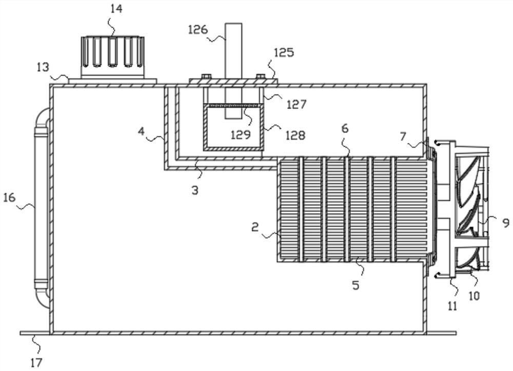
[0022] see figure 1 and 3 , the oil return assembly 12 includes a second flange 125, the second flange 125 is fixedly connected with the fuel tank body 1, and a second oil return pipe 126 is arranged in the upper middle of the second flange 125. A connecting rod 127 is provided under the second flange 125 , and the lower part of the connecting rod 127 is fixedly connected with the filter tank 128 . The upper end of the filter tank 128 is provided with a second filter screen 129 , and the lower end of the second oil return pipe 126 penetrates the first The second filter screen 129 extends to the inside of the filter tank 128, and the second flange 125 is fixedly connected to the oil tank body 1, so that the oil return assembly 12 is easy to disassemble and install, so that after the oil return assembly 12 is used for a long time, the oil return assembly 12. Clean and replace it in time. The returned hydraulic oil enters the filter tank 128 through the second oil return pipe 12...


PUM


Abstract

The hydraulic oil tank comprises an oil tank body, a mounting groove is formed in one side of the oil tank body, a first partition plate is arranged at the position, located on one side of the mounting groove, in the oil tank body, a second partition plate is arranged below the first partition plate, and a plurality of cooling fins distributed at equal intervals are arranged in the mounting groove; a plurality of flow guide pipes arranged in a matrix mode are inserted into the middles of the cooling fins, the two ends of each flow guide pipe communicate with the side walls of the two sides of the mounting groove correspondingly, a mounting frame is arranged on the sides, away from the oil tank body, of the cooling fins, a motor is fixedly mounted on the mounting frame, a connecting ring is arranged on a rotating shaft of the motor, and fan blades are arranged on the outer side of the connecting ring. A protection frame is arranged on the outer sides of the fan blades, and an oil return assembly is arranged at the position, above the installation groove, of the oil tank body. The hydraulic oil tank is simple in structure, high in heat dissipation speed and high in high temperature resistance and corrosion resistance, and the service life of working parts is effectively guaranteed.

Description

technical field [0001] The invention relates to the technical field of hydraulic oil tanks, in particular to a hydraulic oil tank with corrosion resistance and high temperature resistance. Background technique [0002] When the construction machinery is working, driven by the hydraulic pump, the hydraulic oil flows from the oil suction port of the hydraulic oil tank and drives the hydraulic components such as the oil cylinder and the motor through the hydraulic oil circuit to work, and the returned hydraulic oil returns to the oil through the oil return port of the hydraulic oil tank Hydraulic tank [0003] The structure of the existing fuel tank is as follows: it includes the fuel tank, and the fuel tank may be provided with a partition, and the partition divides the fuel tank into a cold oil area and a hot oil area, and the existing fuel tank usually has the following shortcomings: There is no suitable channel between the zones, and the high temperature hydraulic oil in t...

Claims


Application Information

Patent Timeline
IPC IPC(8): F15B1/26F15B21/041F15B21/0423
CPCF15B1/26F15B21/041F15B21/0423
Inventor 蒋振华
Owner 上海钦滨新材料科技有限公司
Why Eureka
Try Eureka