Laser device

A laser and laser cavity technology, applied in the field of lasers, can solve problems such as output wavelength changes

Inactive Publication Date: 2004-04-21
BRITISH TELECOMM PLC
View PDF0 Cites 0 Cited by
  • Summary
  • Abstract
  • Description
  • Claims
  • Application Information

AI Technical Summary

Problems solved by technology

The disadvantage of these distributed feedback lasers is that the output wavelength varies with the temperature of the semiconductor material due to the temperature-dependent refractive index of the semiconductor material

Method used


Image

  • Laser device
  • Laser device
  • Laser device

Examples


Embodiment Construction

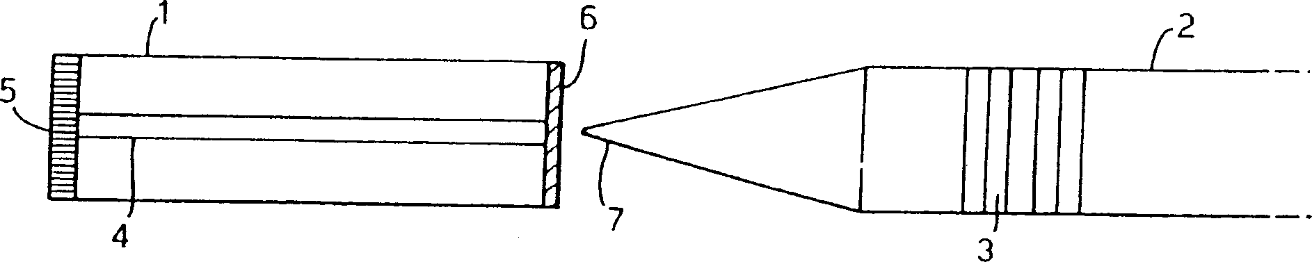
[0032] figure 1 It is a schematic diagram of a prior art fiber grating laser, which includes a semiconductor laser diode 1 aligned with an optical fiber 2 with a grating 3 written in the fiber by ultraviolet light. The semiconductor laser diode 1 comprises an optical waveguide 4 for guiding optical radiation between its rear facet 5 and front facet 6 . The back facet 5 can be plated with a high-reflectivity multi-layer dielectric film, so as to improve its reflectivity in addition to the Fresnel reflection to the semiconductor / air interface. The front flat 6 of the semiconductor laser diode 1 is coated with a multi-layer dielectric anti-reflection film. The optical fiber 2 then includes a tapered fiber lens 7 at its end close to the front facet 6 of the semiconductor laser diode 1 . The laser action characteristics of the fiber grating laser in the prior art are mainly determined by the wavelength, reflectivity and bandwidth of the fiber grating 3 . However, the applicant h...


PUM


Abstract

A laser comprising first and second feedback elements defining a laser cavity, and a gain medium within the laser cavity, the gain medium having first and second facets (5, 6) and an optical waveguide (8) for guiding optical radiation between said first and second facets, wherein the second feedback element is wavelength selective, and the optical waveguide (8) is configured to direct optical radiation at an angle theta to the normal of the second facet (6).

Description

technical field [0001] The present invention relates to a laser. Background technique [0002] In optical telecommunication networks, for example, lasers with narrow linewidth outputs are required. Such lasers can be used, for example, in wavelength-division multiplexing systems where densely packed different wavelengths are utilized to transmit different channels, or in high-bit-rate systems where narrow linewidth sources are required to avoid dispersion effects . Distributed feedback (DFB) semiconductor lasers with diffraction gratings in semiconductor gain materials have been utilized for these applications. A disadvantage of these distributed feedback lasers is that, due to the temperature-dependent refractive index of the semiconductor material, its output wavelength varies with its temperature. This usually requires the use of a temperature controller and associated electronics to stabilize the temperature of the profile feedback laser and thus its output wavelength...

Claims


Application Information

Patent Timeline
Patent Type & Authority Patents(China)
IPC IPC(8): H01S5/10H01S5/14H01S5/227
CPCH01S5/10H01S5/101H01S5/2272H01S5/1064H01S5/1014H01S5/146
Inventor R・J・卡姆贝尔R・瓦特G・谢尔若克J・R・阿尔米塔格M・C・布里尔莱R・A・佩尼D・威廉斯M・J・罗伯森H・J・维克斯
Owner BRITISH TELECOMM PLC
Why Eureka
Try Eureka