A liquid crystal device, preparation method and imaging polarization detection system

A liquid crystal device and liquid crystal technology, applied in the field of target detection, can solve problems such as not considering the polarization characteristics of the target detection object

Active Publication Date: 2019-03-22
NANJING UNIV
View PDF5 Cites 0 Cited by
  • Summary
  • Abstract
  • Description
  • Claims
  • Application Information

AI Technical Summary

Problems solved by technology

The traditional detection system does not consider the polarization characteristics of the target detection object, and the existing polarization detection system still has problems in terms of final performance, technical difficulty and price

Method used


Image

  • A liquid crystal device, preparation method and imaging polarization detection system
  • A liquid crystal device, preparation method and imaging polarization detection system
  • A liquid crystal device, preparation method and imaging polarization detection system

Examples


Embodiment 1

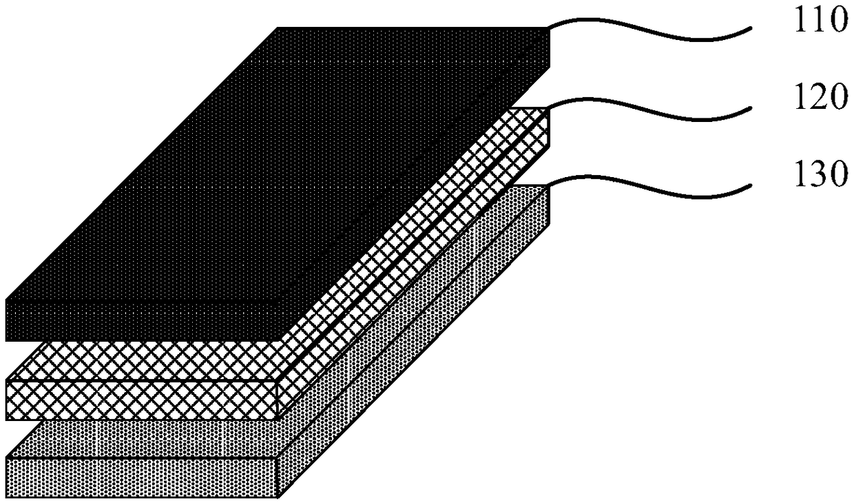
[0049] figure 1 A schematic structural diagram of a liquid crystal device provided in Embodiment 1 of the present invention, as shown in figure 1 As shown, the liquid crystal device provided by the embodiment of the present invention includes: a substrate 130 , an alignment film 120 disposed on one side of the substrate 130 , and a liquid crystal layer 110 disposed on a side of the alignment film 120 away from the substrate. The alignment film 120 has a control pattern in which the molecular director distribution is a predetermined distribution, so that the liquid crystal molecules in the liquid crystal layer 110 self-assemble to form a predetermined liquid crystal focal cone domain array.

[0050] The control patterns on the alignment film 120 can be obtained by means of rubbing alignment or photo-controlled alignment. When the control patterns on the alignment film 120 are obtained by photo-controlled alignment, the alignment film 120 is a photo-controlled alignment film.

...

Embodiment 2

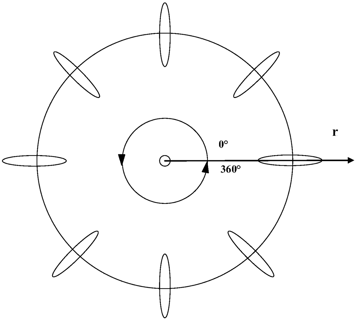
[0055] This embodiment is based on the above-mentioned embodiments, and the difference is that, based on the above-mentioned embodiments, the alignment film has a control pattern in which the molecular director is gradually distributed around the central singular point or the molecular orientation of the alignment film Checkerboard control graphics with vector distributions in orthogonal orientations.

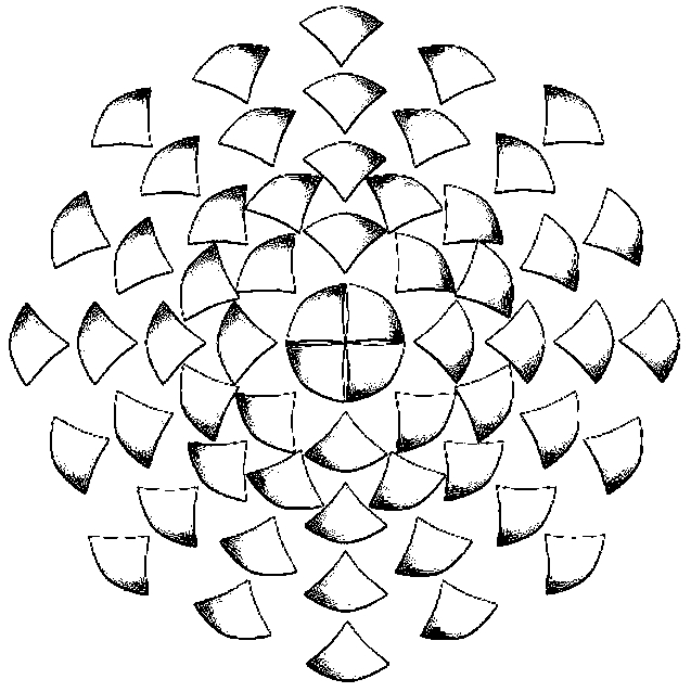
[0056] Figure 3a It is a structural schematic diagram of a radially distributed liquid crystal focal cone domain array, such as Figure 3a As shown, the radially distributed liquid crystal focal cone domain array includes a plurality of liquid crystal focal cone domain units with broken rotational symmetry, and the symmetry axes of the liquid crystal focal cone domain array are all along the radial direction. Figure 3b It is a schematic diagram of the layered structure of a liquid crystal focal cone domain unit, such as Figure 3b As shown, the liquid crystal focal cone dom...

Embodiment 3

[0063] The embodiment of the present invention also provides a method for preparing a liquid crystal device, Figure 5 A schematic structural diagram of a method for preparing a liquid crystal device provided in Embodiment 3 of the present invention, as shown in Figure 5 As shown, the method includes the following operations:

[0064] S110, forming an alignment film on one side of the substrate.

[0065] Optionally, the alignment film formed on one side of the substrate is a photo-controlled alignment film. Before forming the photo-controlled alignment film, in order to increase the wettability and adhesion between the photo-controlled alignment film and the substrate, perform ultrasonic cleaning with ITO washing solution (mixed reagents such as acetone and alcohol) for 30 minutes, and then ultrasonically clean with ultrapure water Twice, each cleaning time is 10 minutes. After drying in an oven at 120° C. for 40 minutes, UVO (ultraviolet ozone) cleaning was performed for ...


PUM


Abstract

The embodiment of the invention discloses a liquid crystal device, a preparation method and an imaging polarization detection system. The liquid crystal device comprises: a substrate, an alignment film disposed on one side of the substrate, and a liquid crystal layer disposed on a side of the alignment film away from the substrate; the alignment film has a control pattern in which the distribution of molecular directors is a set distribution so that the liquid crystal molecules in the liquid crystal layer self-assemble to form a set liquid crystal focal cone domain array; the liquid crystal focal cone domain array includes a plurality of liquid crystal focal cone domain units with broken rotational symmetry. Embodiments of the present invention provide a liquid crystal device, a preparation method and an imaging polarization detection system, so as to accurately obtain the polarization characteristics of the target detection object while imaging the target detection object.

Description

technical field [0001] Embodiments of the present invention relate to target detection technology, and in particular to a liquid crystal device, a preparation method and an imaging polarization detection system. Background technique [0002] The human eye can perceive the amplitude and wavelength information of light, but it is not sensitive to the polarization of light. As an important information of light, the detection technology of polarization is widely used in various fields such as science, technology and industry. For example, detection of hidden or camouflaged targets; detection and identification of surface targets; navigation in smoky climates; medical diagnosis, such as cancer and burn diagnosis; spaceborne or airborne remote sensing; combine etc. [0003] The current polarization detection system generally has a polarizer, a wave plate or even a filter rotating device controlled by manpower or a motor, and the light intensity sensor detects the change of light ...

Claims


Application Information

Patent Timeline
Patent Type & Authority Patents(China)
IPC IPC(8): G02F1/1333G02F1/1337G01J4/00
CPCG02F1/1333G02F1/1337G01J4/00G01J4/04
Inventor 胡伟马玲玲唐明劼葛士军陈鹏陆延青徐飞
Owner NANJING UNIV
Why Eureka
Try Eureka