Automatic testing system of polarization device

A technology for automatic testing and polarizing devices, which is applied in testing optical properties and other directions, and can solve problems such as non-uniformity of liquid crystal thickness and distortion

Pending Publication Date: 2022-07-05
SUN YAT SEN UNIV
View PDF0 Cites 0 Cited by
  • Summary
  • Abstract
  • Description
  • Claims
  • Application Information

AI Technical Summary

Problems solved by technology

In order to meet the needs of practical applications, high-performance liquid crystal-on-silicon spatial light modulators are very important, but the performance of the device will be limited by the inhomogeneity of the spatial distribution of liquid crystal molecules: 1) the inhomogeneity of liquid crystal thickness; 2 ) The liquid crystal molecules may be "distorted" under the change of the applied voltage; 3) The liquid crystal molecules close to the alignment layer are not sensitive to the change of the applied voltage

Method used


Image

  • Automatic testing system of polarization device
  • Automatic testing system of polarization device
  • Automatic testing system of polarization device

Examples


Embodiment Construction

[0040] The technical solutions in the embodiments will be clearly and completely described below with reference to the drawings in the embodiments. Obviously, the described embodiments are only a part of the embodiments, not all of the embodiments.

[0041] In the embodiments, it is to be understood that the terms "middle", "upper", "lower", "top", "right side", "left end", "above", "back", "middle", etc. indicate The orientation or positional relationship is based on the orientation or positional relationship shown in the accompanying drawings, only for the convenience of description, rather than indicating or implying that the device or element referred to must have a specific orientation, be constructed and operated in a specific orientation, and therefore cannot be It is understood as a limitation of the present invention. Unless otherwise defined, technical or scientific terms used in this disclosure shall have the ordinary meaning as understood by one of ordinary skill i...


PUM


Abstract

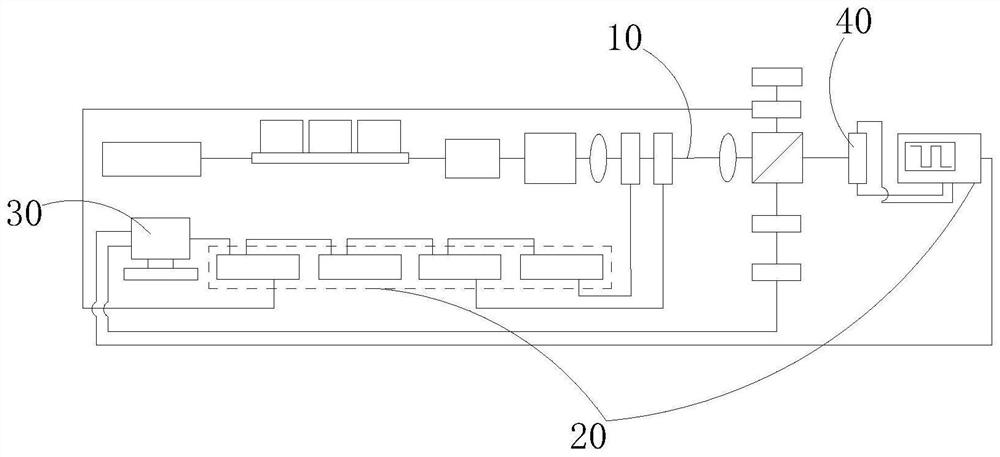
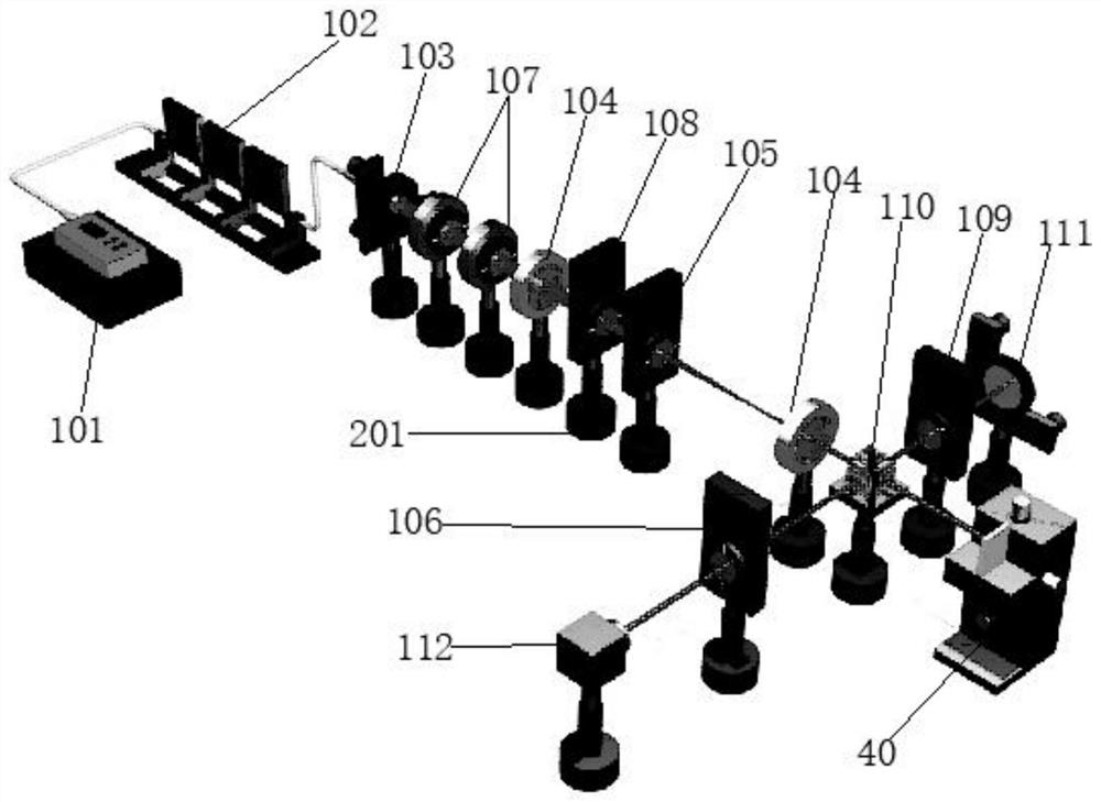
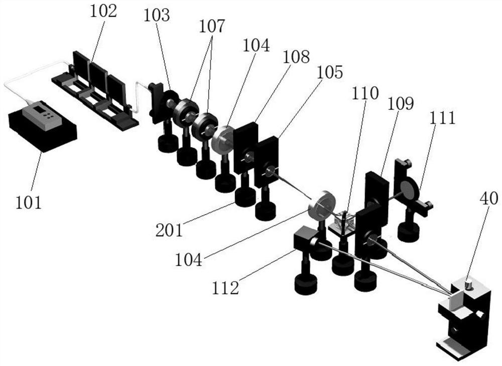
The invention discloses an automatic test system of a polarization device. The automatic test system comprises a test light path assembly and an automatic control module, the test light path assembly is used for testing polarization response and/or phase response of the polarization device and is provided with at least one optical lens group, at least one tunable laser module, at least one photoelectric detector and at least one camera; and the automatic control module is provided with at least one adjusting mechanism, is used for driving the at least one optical lens group to rotate to change the orientation of the optical axis, and is linked with the at least one tunable laser module and/or the at least one photoelectric detector and/or the at least one camera. The automatic test system of the polarization device has the advantages of adjustable wavelength, adjustable power, adjustable polarization state, automatic control and the like, and can realize automatic measurement of polarization response and phase response according to a polarization analysis method and an interference method.

Description

technical field [0001] The invention relates to the technical field of optoelectronic devices, in particular to an automated testing system for polarization devices. Background technique [0002] Diffraction, interference and polarization of light can confirm the wave nature of light. Therefore, light can be used as a carrier to control the amplitude, polarization, phase, frequency and other processes of information emission, transmission, reception, and storage. As the core component to realize the dynamic regulation of light field, spatial light modulator has broad application prospects in the fields of digital holography, mode multiplexing in optical communication systems, and lidar ranging. [0003] From digital holography technology to optical communication modules, to in-vehicle lidars for autonomous driving, which have been popular in recent years, spatial light modulators play an important role. The core element of the spatial light modulator is liquid crystal on si...

Claims


Application Information

Patent Timeline
Patent Type & Authority Applications(China)
IPC IPC(8): G01M11/02
CPCG01M11/02G01M11/0228G01M11/0271
Inventor 陈钰杰李嘉麒朱照祥余思远
Owner SUN YAT SEN UNIV
Why Eureka
Try Eureka