
Control method of cell localization probe

A cell positioning and control method technology, applied in the control field of cell positioning probes, can solve problems such as increased system cost and complexity, reduced system success rate, and low control accuracy, so as to improve work efficiency and stability, and increase average Speed, improve the effect of finding efficiency

Pending Publication Date: 2022-07-05
CHINA INNOVATION INSTR CO LTD
View PDF0 Cites 0 Cited by
  • Summary
  • Abstract
  • Description
  • Claims
  • Application Information

AI Technical Summary

Problems solved by technology

The traditional probe contact detection method usually requires additional auxiliary equipment for the system, such as: force sensor, microscope lens, etc., which increases the cost and complexity of the system; in addition, there are fewer needle tip contact detection algorithms, but the control accuracy low, poor applicability
Moreover, most researchers find cells by controlling the probe at a constant speed, which is inefficient and the tip of the needle is fragile, resulting in abnormal data
[0004] The existing methods mainly use contact force sensors and binocular vision to detect the contact of cells, which can realize the contact detection between the needle tip and the bottom surface, but increase the complexity of the microinjection system and the control algorithm, and increase the cost; The sliding distance of the needle tip is used to judge the contact between the needle tip and the bottom surface, but when the bottom surface is a non-smooth surface, the algorithm fails and the applicability is poor
In addition, some people descend a fixed distance based on prior data. This method has low control accuracy, and often leads to a decrease in the success rate of the system due to the lack of contact with the cells.

Method used


Image

  • Control method of cell localization probe
  • Control method of cell localization probe
  • Control method of cell localization probe

Examples


Embodiment 1

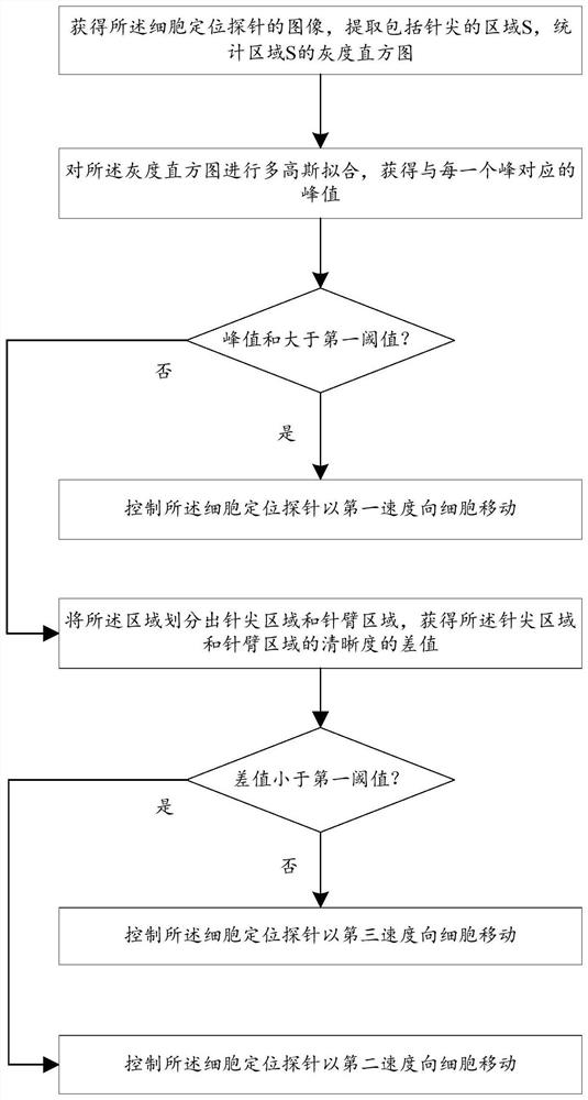
[0027] figure 1 The flow chart of the control method of the cell localization probe in Example 1 of the present invention is schematically presented, as figure 1 As shown, the control method of the cell localization probe includes speed control of the cell localization probe, and the speed control method is:

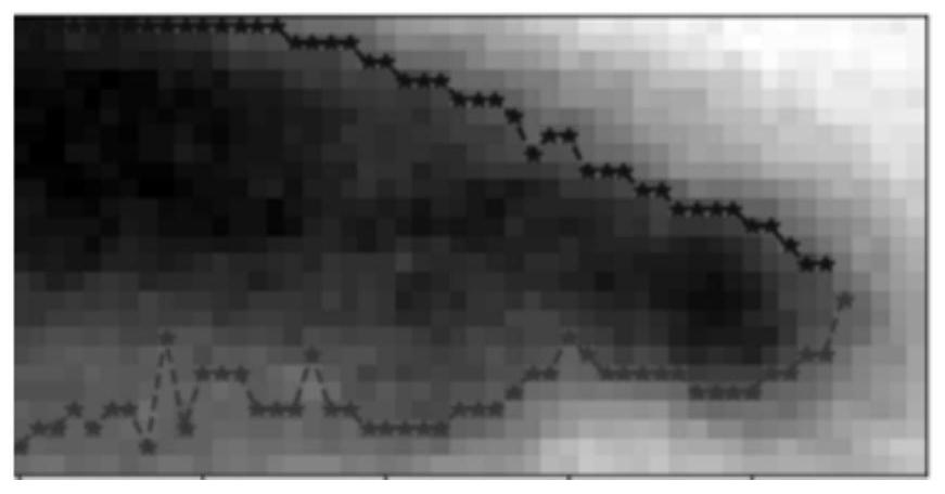
[0028] To obtain an image of the cell localization probe, extract the region S including the tip, as figure 2 shown, the grayscale histogram of the statistical region S;

[0029] Perform multi-Gaussian fitting on the grayscale histogram, such as image 3 shown, obtain the peak value A corresponding to each peak i , i=1,2...n, N is an integer not less than 2;

[0030] If the peak and H 1 is the first threshold, the peak and as Figure 4 As shown, control the cell localization probe at a first velocity v 1 move to cells

[0031] If the peak and Divide the area S into a needle tip area and a needle arm area, and obtain the difference ΔR between the sharpness of...

Embodiment 2

[0050] An application example of the control method of the cell localization probe according to Embodiment 1 of the present invention.

[0051] like figure 1 As shown, the control method of the cell localization probe includes the speed control of the cell localization probe, and the speed control method is as follows:

[0052] To obtain an image of the cell localization probe, extract the region S including the tip, as figure 2 shown, the grayscale histogram of the statistical region S;

[0053] Three Gaussian fitting is performed on the grayscale histogram, such as image 3 shown, obtain the peak value A corresponding to each peak i , i=1, 2...N, N=3;

[0054] If the peak and H 1 =50, the peak sum as Figure 4 As shown, control the cell localization probe at a first velocity v 1 move to cells

[0055] If the peak and The area S is divided into a needle tip area and a needle arm area, and the division method is as follows:

[0056] Extract the edge of the area S...


PUM


Abstract

The invention provides a control method of a cell localization probe, which comprises the speed control of the probe, and the speed control comprises the following steps: obtaining an image of the probe, extracting an area S comprising a needle tip, and counting a gray level histogram of the area S; performing multi-Gaussian fitting on the gray level histogram to obtain a peak value Ai corresponding to each peak, i = 1, 2... n, and N is an integer not less than 2; if the peak value and the H1 are first threshold values, controlling the probe to move towards the cell at a first speed v1; if the peak sum is obtained, the area S is divided into a needle point area and a needle arm area, and the difference value delta R of the sharpness of the needle point area and the needle arm area is obtained; if the difference value delta R is smaller than R1, and R1 is a second threshold value, the probe is controlled to move towards the cells at a second speed v2; if the difference value delta R is larger than or equal to R1, the probe is controlled to move towards the cells at a third speed v3, and v2 is larger than v3 and smaller than v1. The device has the advantages of high probe moving efficiency, accurate judgment and the like.

Description

technical field [0001] The present invention relates to cell analysis, in particular to a control method of a cell localization probe. Background technique [0002] When analyzing cells with single-cell mass spectrometry systems, it is essential to control where the probes locate and make light contact with the cells. Therefore, it is necessary to control the probe to descend from the cell surface to the cell surface, and stop moving after contacting the cell. However, in this process, when the probe descends too fast, the needle tip is often broken; when the probe descends slowly, the work efficiency of the system is greatly reduced. Therefore, the control of the movement speed of the needle tip is very important; Over-contact or non-contact with cells in the Z direction (vertical to the stage) results in abnormal analysis results. It is of great significance to accurately detect whether the needle tip is in contact with cells in the Z direction. [0003] With the develop...

Claims


Application Information

Patent Timeline
Patent Type & Authority Applications(China)
IPC IPC(8): G01N33/487G06T7/70
CPCG01N33/48728G06T7/70G01Q10/065G01Q20/02
Inventor 闻路红陈安琪甘剑勤闫明月胡舜迪
Owner CHINA INNOVATION INSTR CO LTD
Learn More