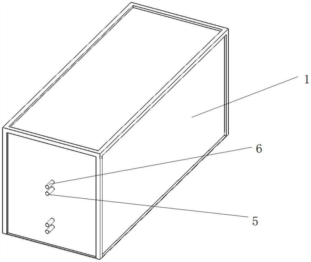
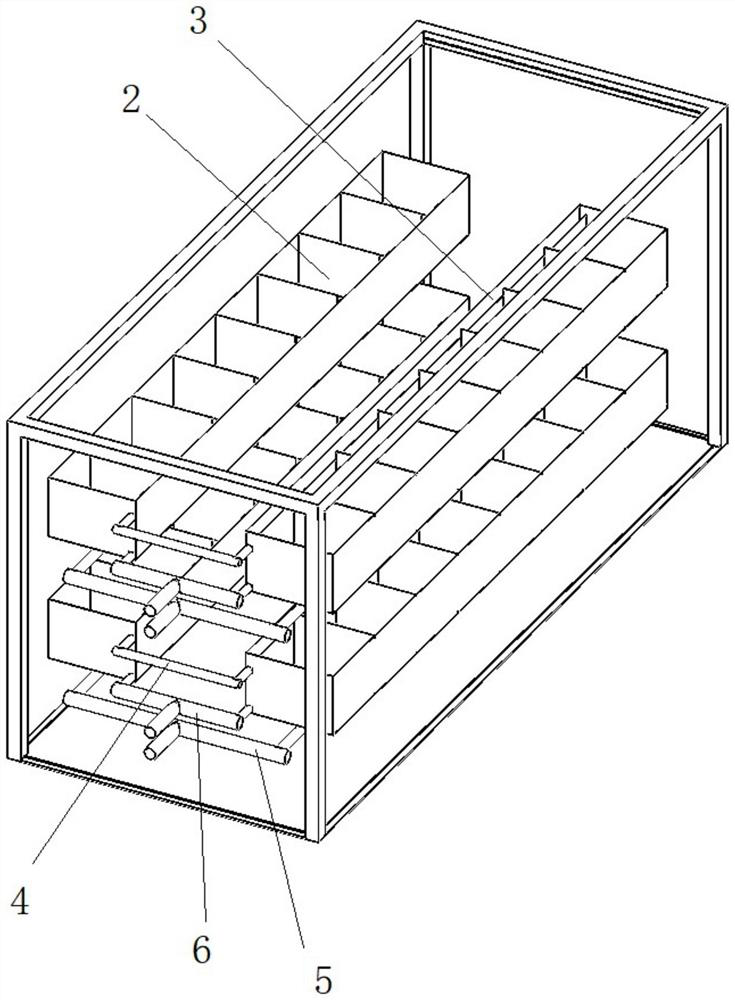
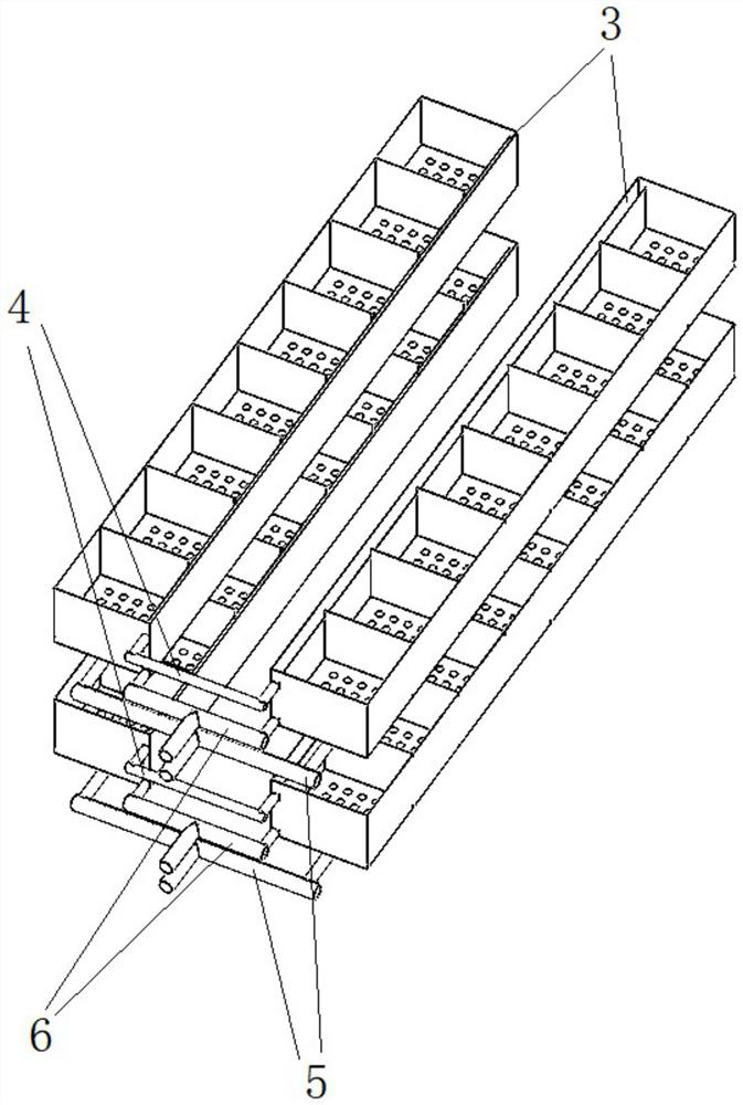
Extensible server container with liquid cooling system

A container and server technology, applied in the server field, can solve the problems of high cost, high leakage risk, and many pipeline interfaces, and achieve the effects of small environmental temperature influence, good scalability, and simple pipeline layout

Pending Publication Date: 2022-07-05
清链科技(北京)有限公司
View PDF0 Cites 0 Cited by
  • Summary
  • Abstract
  • Description
  • Claims
  • Application Information

AI Technical Summary

Problems solved by technology

This change directly causes the heat dissipation of the data center to increase from the original several kilowatts to several hundred kilowatts. The power density of the data center computer room continues to increase, which poses a challenge to the cooling system of the data center computer room.
[0003]The traditional heat dissipation method of the data center computer room is to cool down the data center computer room equipment such as servers by reducing the temperature of the entire data center computer room. This method not only wastes electricity but also It has little effect and cannot completely solve the hot spot problem in the data center. Many data centers have problems such as high cost of refrigeration equipment and transportation, poor maintainability and scalability, etc.
[0004] In the existing server cooling solution, the liquid cooling system is tightly coupled with the rack and equipment, which brings many difficulties to pipeline layout, rack design, equipment wiring, equipment maintenance and installation, and the cost is very high
Moreover, the cold plate is generally placed directly on each main heat source, and the coolant flows through the cold plate to take away the heat of the heat source. There are many pipe connections, and the risk of leakage is high.

Method used


Image

  • Extensible server container with liquid cooling system
  • Extensible server container with liquid cooling system
  • Extensible server container with liquid cooling system

Examples


Embodiment Construction

[0018] In order to understand the above objects, features and advantages of the present invention more clearly, the present invention will be further described in detail below with reference to the accompanying drawings and specific embodiments.

[0019] In the description of the present invention, it should be understood that the terms "center", "portrait", "horizontal", "top", "bottom", "front", "rear", "left", "right", " The orientation or positional relationship indicated by vertical, horizontal, top, bottom, inner, outer, etc. is based on the orientation or positional relationship shown in the drawings, and is only for the convenience of describing the present invention and The description is simplified rather than indicating or implying that the device or element referred to must have a particular orientation, be constructed and operate in a particular orientation, and therefore should not be construed as limiting the invention. In addition, the terms "first", "second", ...


PUM


Abstract

The invention provides an extensible server container with a liquid cooling system, and relates to the field of servers, the extensible server container comprises an external shell, an internal cabinet and a cooling liquid distribution unit; the internal cabinet specifically comprises a plurality of cooling tanks used for placing server monomers, the bottoms of the plurality of cooling tanks are communicated and allow cooling liquid to enter, one side of each cooling tank is further provided with a hot liquid interlayer used for receiving heat-carrying liquid, and the plurality of cooling tanks share one hot liquid interlayer; the cooling liquid distribution unit specifically comprises a balance pipe, a liquid inlet pipe and a liquid discharge pipe, the liquid inlet pipe is communicated with the bottom of the cooling tank, the liquid discharge pipe is communicated with the bottom of the hot liquid interlayer, and the balance pipe is communicated with the upper part of the hot liquid interlayer, so that liquid higher than the upper liquid level in the hot liquid interlayer flows out of the hot liquid interlayer. The system is high in cooling efficiency, good in expandability, obvious in energy-saving advantage, uniform in cooling, free of local overheating and small in influence on the environment temperature.

Description

technical field [0001] The invention relates to the field of servers, in particular to an expandable server container with a liquid cooling system. Background technique [0002] With the rapid improvement of equipment performance and the significant increase in power density, the application of high-performance rack and blade servers and storage devices is becoming more and more common, and virtualization technology is increasingly used to consolidate servers and storage. This change directly leads to the increase of the cooling capacity of the data center from several kilowatts to several hundreds of kilowatts. [0003] The traditional cooling method of the data center computer room is to reduce the temperature of the entire data center computer room to achieve the purpose of cooling the server and other data center equipment room equipment. This method not only wastes power, but also has little effect. It cannot completely solve the hotspot problem of the data center. The...

Claims


Application Information

Patent Timeline
Patent Type & Authority Applications(China)
IPC IPC(8): H05K7/20
CPCH05K7/20272H05K7/20236H05K7/20263Y02D10/00
Inventor 王彧薇王承顺刘梦衣王承志成文强
Owner 清链科技(北京)有限公司
Why Eureka
Try Eureka