Check patentability & draft patents in minutes with Patsnap Eureka AI!

In-plane rod sliding mechanism

A sliding mechanism and plane technology, applied in processing drive devices, additive processing, etc., can solve problems such as difficult synchronous operation of two sets of motors, increased consumption of 3D printing equipment, and unstable operation of motors

Pending Publication Date: 2022-07-08
涂征宇工业设计温州有限公司
View PDF0 Cites 0 Cited by
  • Summary
  • Abstract
  • Description
  • Claims
  • Application Information

AI Technical Summary

Problems solved by technology

[0002] In recent years, with the continuous progress and development of society, people's living standards are also increasing, and some emerging industries are gradually increasing. Some of these emerging industries and industries will use 3D printing equipment when developing products. Print the required products to realize the simulation effect on the research and development items in advance. However, when the 3D printing equipment is running, it is necessary to install multiple sets of power motors to run at the same time to ensure the stability of the 3D printing equipment during operation. A single motor will appear unstable. , problems such as uneven force
[0003] However, as far as the existing 3D printing equipment is concerned, it is necessary to install two sets of motors on the horizontal rod of the driving plane. The multiple sets of motors installed will increase the consumption of the 3D printing equipment. If the transmission belt becomes loose, the two sets of motors will be difficult to The problem of achieving synchronous operation

Method used


Image

  • In-plane rod sliding mechanism
  • In-plane rod sliding mechanism
  • In-plane rod sliding mechanism

Examples


Embodiment

[0035] Example: please refer to Figure 1 to Figure 9 :

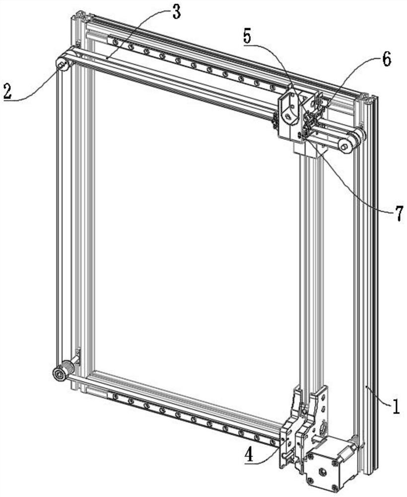
[0036] The present invention proposes an in-plane rod sliding mechanism, comprising: a main frame assembly 1 ; a guide wheel component 2 is rotatably mounted on the main frame assembly 1 .

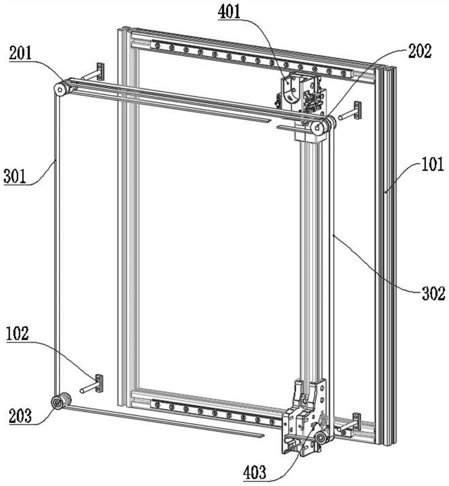
[0037] In addition, according to the embodiment of the present invention, the main frame assembly 1 includes: an installation frame 101, the installation frame 101 is formed of a frame structure by fixing rods, and four sets of installation columns 102 are arranged on the outer side of the installation frame 101, and each group is installed The column 102 is stably fixed by screws, and the mounting column 102 is set to be fixed on the mounting frame 101 by two sets of screws, which can not only adjust the corresponding position of the mounting column 102, but also make the mounting column 102 more stable after fixing. 102 has a "T"-shaped structure, and the installation column 102 is set to a "T"-shaped structure, so that the insta...

Embodiment 2

[0041] It includes: a transmission part 3 is wound and installed on the guide wheel part 2 , and a sliding part 4 is slidably installed on the main frame assembly 1 .

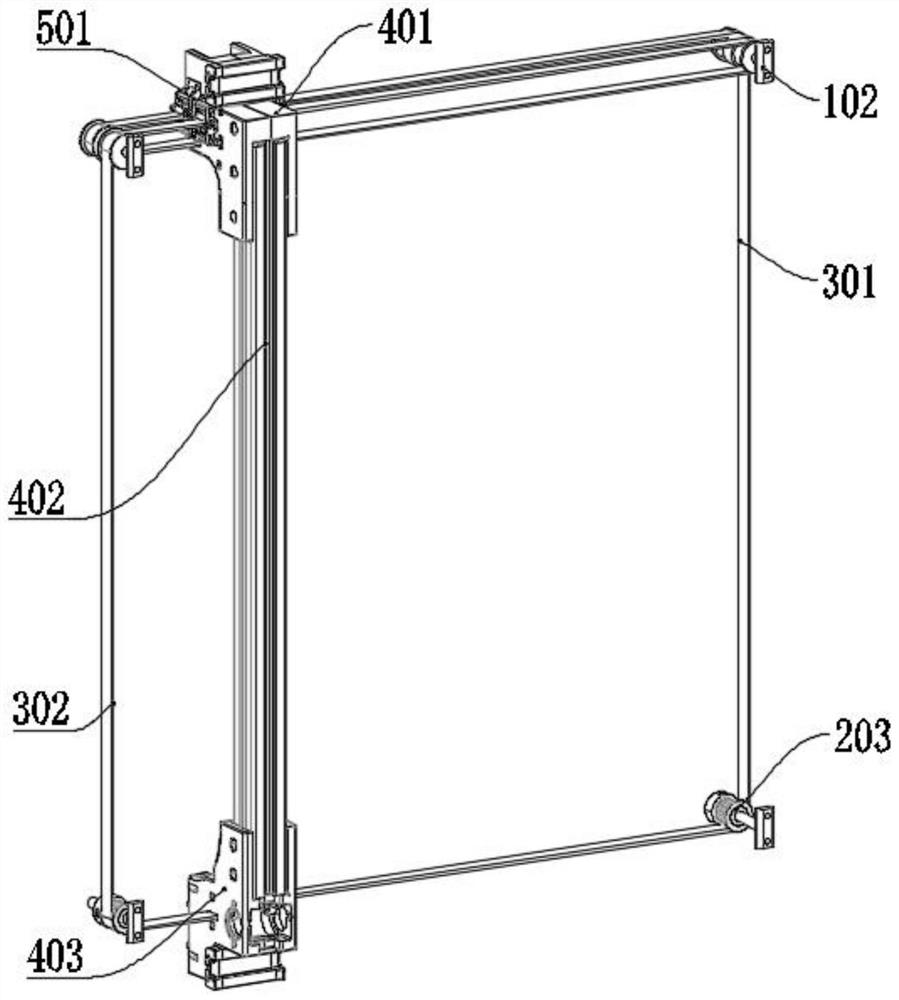
[0042] In addition, according to the embodiment of the present invention, the transmission member 3 includes: an outer timing belt 301, the outer timing belt 301 is wound on the guide wheel member 2 at the outer end portion, and the end of the outer timing belt 301 is connected with the sliding member 4, The inner synchronous belt 302 is wound on the guide wheel member 2 at the inner end position, and the ends of the same inner synchronous belt 302 are connected with the sliding member 4, and the outer synchronous belt 301 and the inner synchronous belt 302 are wound on the guide wheel member 2, and The ends of the inner synchronous belt 302 and the outer synchronous belt 301 are both connected to the sliding member 4, so that the outer synchronous belt 301 and the inner synchronous belt 302 form a closed frame ...

Embodiment 3

[0046] Including: the position of the sliding part 4 is provided with the installation part 5, the buffer assembly 6 is slidably installed on the installation part 5, the sliding part 4 is installed with the tensioning assembly 7 through the adjusting assembly 8, and the transmission part 3 is installed on the sliding part through the tensioning assembly 7. 4 on.

[0047] In addition, according to the embodiment of the present invention, the installation part 5 includes: an installation block 501, the installation block 501 is fixed on the outer wall of the sliding part 4, and the installation block 501 has two structures of inclination and vertical. 501 is set in two structures of inclination and vertical, so that the buffer assembly 6 can be more stably installed on the subsequent installation block 501. The front and rear positions of the top of the installation block 501 are provided with protruding heads 502, and the protruding heads 502 are arranged on the installation bl...


PUM


Abstract

The invention provides an in-plane rod sliding mechanism, and relates to the technical field of 3D printing equipment. A guide wheel component is rotationally installed on the main frame assembly, transmission components are installed on the guide wheel component in a winding mode, the two sets of transmission components form a composite frame structure, and the two ends of each transmission component are fixed to the two ends of the corresponding sliding component at the same time. The running guide wheel part can provide force with the same size and direction for the transmission part, the problem that the two ends of the sliding part are uneven in stress and incline is avoided, meanwhile, the motor can be installed at any position of the guide wheel part, and the guide wheel part and the motor can be installed at any position. The problem that equipment installation is affected by motors is avoided, and the problems that according to existing 3D printing equipment, in order to keep stable operation of a plane transverse rod, two or more sets of motors can be installed, and consequently the equipment manufacturing cost is high, and the use power consumption is increased are solved.

Description

technical field [0001] The invention relates to the technical field of 3D printing equipment, in particular to an in-plane rod sliding mechanism. Background technique [0002] In recent years, with the continuous progress and development of society, people's living standards are also increasing, and some emerging industries are also gradually increasing. Some of these emerging industries and industries will use 3D printing equipment when developing products. Print the required products to realize the advance simulation effect on the research and development items, but the 3D printing equipment is running, and multiple sets of power motors need to be installed to run at the same time to ensure the stability of the 3D printing equipment during operation. A single motor may run unstable. , uneven force and other problems. [0003] However, as far as the current 3D printing equipment is concerned, two sets of motors need to be installed on the horizontal rod of the driving plan...

Claims


Application Information

Patent Timeline
Patent Type & Authority Applications(China)
IPC IPC(8): B29C64/227B33Y30/00
CPCB29C64/227B33Y30/00
Inventor 涂征宇
Owner 涂征宇工业设计温州有限公司
Features
  • R&D
  • Intellectual Property
  • Life Sciences
  • Materials
  • Tech Scout
  • Unparalleled Data Quality
  • Higher Quality Content
  • 60% Fewer Hallucinations
Learn More