
Hydraulic cylinder system, hydraulic walking beam and working method of hydraulic walking beam

A hydraulic cylinder and hydraulic source technology, applied in the field of hydraulic cylinders, can solve problems such as unbalanced power output of hydraulic pump stations, heating of hydraulic sources, and easy failure of hydraulic sources, etc., to improve energy recovery effects, meet working conditions, and maintain good performance. The effect of the energy saving effect

Pending Publication Date: 2022-07-08
WISDRI ENG & RES INC LTD
View PDF0 Cites 0 Cited by
  • Summary
  • Abstract
  • Description
  • Claims
  • Application Information

AI Technical Summary

Problems solved by technology

This working condition will cause the power output of the hydraulic pump station to be very unbalanced. When the walking beam is lowered, the energy is not fully utilized, which causes energy waste to a certain extent. At the same time, the back pressure in this case will cause the hydraulic source A large amount of heat is generated, and the hydraulic source is prone to failure. In order to ensure the normal operation of the hydraulic source, more cooling water will be consumed

Method used


Image

  • Hydraulic cylinder system, hydraulic walking beam and working method of hydraulic walking beam
  • Hydraulic cylinder system, hydraulic walking beam and working method of hydraulic walking beam
  • Hydraulic cylinder system, hydraulic walking beam and working method of hydraulic walking beam

Examples


Embodiment 1

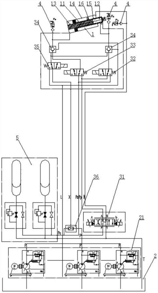
[0034] like figure 1 , Figure 3-Figure 6 , the embodiment of the present invention provides a hydraulic cylinder system, including a hydraulic cylinder 1, an accumulator 5, a valve control mechanism, and a hydraulic source 2 with an oil supply port and an oil return port.

[0035] like figure 1 , Figure 3-Figure 6 , the hydraulic cylinder 1 includes a cylinder barrel 14, a piston rod 15, and a piston connected to the piston rod 15 and slidably arranged in the cylinder barrel 14. The cylinder barrel 14 is provided with a guide column 16, and the The piston rod 15 is a hollow piece and is sleeved on the guide post 16 . The piston, the piston rod 15 and the cylinder 14 cooperate to form a rod cavity 11 , and the piston rod 15 and the The first rodless cavity 12 is formed by the guide column 16 , and the second rodless cavity 13 is formed by the piston, the guide column 16 and the cylinder 14 . Preferably, the above-mentioned piston is connected to the end of the piston rod ...

Embodiment 2

[0046] An embodiment of the present invention provides a hydraulic walking beam, comprising a walking beam body, a lifting hydraulic cylinder for driving the walking beam body to lift and lower, and a translation hydraulic cylinder for driving the walking beam body to translate. The lifting hydraulic cylinder adopts the hydraulic cylinder system provided in the first embodiment.

[0047] The present invention also relates to the working method of the above-mentioned hydraulic walking beam, and the working method includes:

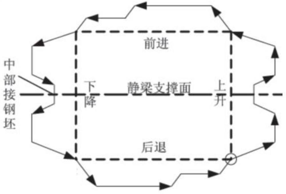
[0048] Taking the support surface of the static beam as the boundary, the actions of the walking beam above the support surface of the static beam are defined as full-load up and full-load down, respectively, and the actions of the walking beam below the static beam support surface are respectively no-load down and no-load up;

[0049] No-load ascent process: through the valve control in the hydraulic cylinder system, the accumulator 5 supplies pressure oil...

Embodiment 3

[0065] Combine the following Figure 2 to Figure 6 , for the above-mentioned specific hydraulic walking beam, its working process is roughly described as follows:

[0066] The operation of the billet in the furnace is completed by the ascending → forward → descending → backward of the walking beam body. During the rising and descending process of the billet, such as figure 2 , taking the support surface of the static beam as the boundary, the actions above the support surface of the static beam are full-load rise and full-load descent, respectively, and the actions below the static beam support surface are no-load descent and no-load rise, respectively.

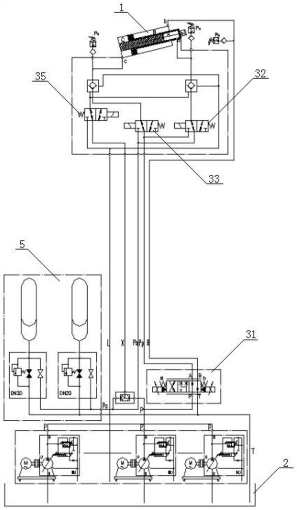
[0067] No-load ascent process: such as image 3 , the second directional control valve 32 and the third directional control valve 33 are in the left position; the first directional control valve 31 is in the right position; the reversing control valve 35 is in the left position, and the two one-way valves 34 are in the open...


PUM


Abstract

The invention relates to a hydraulic cylinder system which comprises a hydraulic cylinder, an energy accumulator, a valve control mechanism and a hydraulic source with an oil supply port and an oil return port. The hydraulic cylinder is provided with a rod cavity and two rodless cavities, and the rod cavity is communicated with the oil supply port and the oil return port respectively; the two rodless cavities are respectively communicated with the oil supply port, the oil return port and the energy accumulator; and the energy accumulator, the oil supply port and the oil return port are respectively communicated with one oil cavity of the hydraulic cylinder through the valve control mechanism. In addition, the invention further relates to a hydraulic walking beam adopting the hydraulic cylinder system and a working method of the hydraulic walking beam. The hydraulic spring is provided for the hydraulic cylinder, and the good energy-saving effect is achieved; through the design of a matched oil way, the functions of the two rodless cavities can be exchanged at any time when the variable load occurs in the heavy load descending and ascending process, the working condition requirement can be better met, the energy recovery effect is improved, and the hydraulic walking beam can better meet the working requirements of hydraulic equipment such as a hydraulic walking beam.

Description

technical field [0001] The invention belongs to the technical field of hydraulic cylinders, and in particular relates to a hydraulic cylinder system, a hydraulic walking beam using the hydraulic cylinder system, and a working method of the hydraulic walking beam. Background technique [0002] In modern steel rolling mills, hydraulic stepping heating furnaces have been widely used due to their many advantages. Whether it is sheet, bar or wire, whether it is a new production line or an old factory renovation, hydraulic stepping heating is preferred. furnace. Large and medium-sized walking furnaces are mainly composed of walking beams, lifting ramps, fixed beams and hydraulic drive mechanisms of the walking beams. The rise and fall of the walking beam are driven by the lifting hydraulic cylinder, and the forward and backward are driven by the translation cylinder. When the walking beam lifts the billet, the lifting hydraulic cylinder needs to overcome the entire weight of the...

Claims


Application Information

Patent Timeline
IPC IPC(8): F15B13/02F15B1/02F15B19/00
CPCF15B13/027F15B13/02F15B1/02F15B19/00Y02P70/10
Inventor 刘斌奇江潇韩波武继权张文凤吴欣曹玉亮
Owner WISDRI ENG & RES INC LTD
Learn More