
High-rotating-speed and high-power hydraulic coupler speed regulating device capable of sucking back hydraulic oil

A technology of hydraulic coupling and speed regulating device, which is applied in the direction of fluid pressure actuating device, clutch, fluid clutch, etc., can solve the problem of lack of hydraulic oil suction mechanism, affecting the service life of hydraulic coupling, and shortening the internal key components. Service life and other issues

Pending Publication Date: 2022-07-08
乔转
View PDF0 Cites 0 Cited by
  • Summary
  • Abstract
  • Description
  • Claims
  • Application Information

AI Technical Summary

Problems solved by technology

[0004] 1. The existing hydraulic coupler speed control device lacks a suction mechanism for hydraulic oil. Due to the continuous rotation inside the hydraulic coupler, some debris may be generated. During the circulation of hydraulic oil, debris will Shorten the service life of structures such as turbines;
[0005] 2. The long-term operation of the hydraulic coupling will increase the temperature of the hydraulic oil, which in turn will cause the hydraulic oil inside the speed control device to have a higher temperature. The traditional cooling method only installs cooling fins to speed up heat dissipation and at the same time Increase the temperature of the surrounding environment;
[0006] 3. The existing hydraulic coupler lacks the shock absorption function. Different degrees of vibration may occur during the working process of the hydraulic coupler. If the vibration amplitude is too large, it will shorten the service life of its internal key components, thereby affecting the hydraulic force. Coupler life

Method used


Image

  • High-rotating-speed and high-power hydraulic coupler speed regulating device capable of sucking back hydraulic oil
  • High-rotating-speed and high-power hydraulic coupler speed regulating device capable of sucking back hydraulic oil
  • High-rotating-speed and high-power hydraulic coupler speed regulating device capable of sucking back hydraulic oil

Examples


Embodiment 1

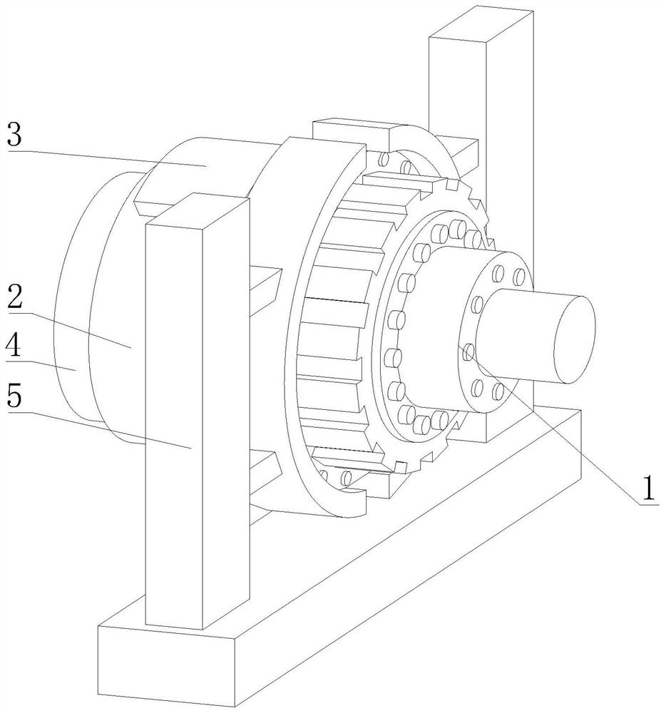
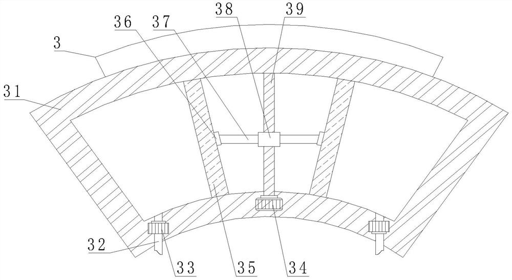
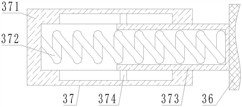
[0041] like Figure 1-7As shown in the figure, the present invention provides a high-speed and high-power hydraulic coupling speed regulating device that can suck back hydraulic oil, including a hydraulic coupling 1, and a speed regulating device 2 is arranged on the left side of the hydraulic coupling 1. The top of the speed device 2 is provided with a back suction mechanism 3, the left side of the speed control device 2 is provided with a cooling mechanism 4, the surface of the hydraulic coupler 1 is provided with a limit mechanism 5, and the back suction mechanism 3 includes a back suction shell 31. A filter plate 35 is fixedly connected to the inner wall of the casing 31 , a No. 1 motor 34 is arranged inside the suction casing 31 , an output end of the No. 1 motor 34 is fixedly connected to a No. 1 threaded rod 39 , and the top of the No. 1 threaded rod 39 is connected to the suction casing 31 . The top of the inner wall is movably connected, the surface of the No. 1 threa...

Embodiment 2

[0044] like Figure 1-7 As shown, on the basis of Embodiment 1, the present invention provides a technical solution: preferably, the cooling mechanism 4 includes a cooling casing 41, the top of the cooling casing 41 is provided with a water tank 42, and the surface of the water tank 42 is provided with a cooling sheet 43, The bottom of the water tank 42 is fixedly connected with a water pipe 45, the surface of the water pipe 45 is provided with a water pump 44, the bottom of the water pipe 45 extends to the inner cavity of the cooling shell 41 and is provided with a water distributor 46, and the bottom of the inner wall of the cooling shell 41 is fixedly connected with a water storage tank 491 A return pipe 492 is fixedly connected to the interior of the water storage tank 491, and the other end of the return pipe 492 extends to the interior of the water tank 42. The surface of the return pipe 492 is provided with a return water pump 493 outside the cooling shell 41. The bottom...

Embodiment 3

[0047] like Figure 1-7 As shown, on the basis of Embodiment 1, the present invention provides a technical solution: preferably, the limiting mechanism 5 includes a shock-absorbing disk 57, and the shock-absorbing disk 57 includes an extrusion shell 571, and the inner wall of the extrusion shell 571 is fixedly connected The limit rod 572 is movably sleeved with a displacement plate 574 on the surface of the limit rod 572 , and a return spring 573 is fixedly connected to the surface of the displacement plate 574 and located outside the limit rod 572 . The inner wall is fixedly connected, the surface of the displacement plate 574 is fixedly connected with a connecting column 575, one end of the connecting column 575 is extended to the outside of the extrusion shell 571 and is fixedly connected with an elastic plate 576, and the surface of the extrusion shell 571 is fixedly connected with a fixed column 56, fixed The other end of the column 56 is fixedly connected with a connecti...


PUM


Abstract

The invention discloses a high-rotating-speed and high-power hydraulic coupler speed regulating device capable of sucking back hydraulic oil, and relates to the technical field of hydraulic couplers, the high-rotating-speed and high-power hydraulic coupler speed regulating device comprises a hydraulic coupler, a speed regulating device is arranged on the left side of the hydraulic coupler, a sucking-back mechanism is arranged at the top of the speed regulating device, and a cooling mechanism is arranged on the left side of the speed regulating device. And a limiting mechanism is arranged on the surface of the hydraulic coupler. Through cooperation of a first motor, a filter plate, a scraper, an extrusion spring and a first threaded block, after the first motor is started, the scraper is driven by the first threaded block to clean the surface of the filter plate, and contact between the scraper and the filter plate is guaranteed under the action of resilience force of the extrusion spring; the problems that due to continuous rotation in the hydraulic coupler, part of chippings can be generated, and the service life of a turbine and other structures can be shortened in the circulation process of hydraulic oil by the chippings are solved, and the chipping filtering effect is achieved.

Description

technical field [0001] The invention relates to the technical field of hydraulic couplers, in particular to a high-speed and high-power hydraulic coupler speed regulating device capable of sucking back hydraulic oil. Background technique [0002] Hydraulic coupling, also known as hydraulic coupling, is a hydraulic transmission device used to connect a power source (usually an engine or a motor) with a working machine and transmit torque by the change of liquid momentum moment. Different, hydraulic couplings are divided into ordinary hydraulic couplings, torque-limiting hydraulic couplings and speed-regulating hydraulic couplings. [0003] The following problems exist for the prior art: [0004] 1. The existing hydraulic coupling speed regulating device lacks a suction mechanism for hydraulic oil. Due to the continuous rotation inside the hydraulic coupling, some debris may be generated. Shorten the service life of turbines and other structures; [0005] 2. The long-term o...

Claims


Application Information

Patent Timeline
Patent Type & Authority Applications(China)
IPC IPC(8): F15B21/041F15B21/0423F16F15/123F16D35/00
CPCF15B21/041F15B21/0423F16F15/123F16D35/00Y02E10/20
Inventor 乔转
Owner 乔转
Learn More