Pneumatic separation recoverable carrier rocket for launching sub-orbital load

A technology for aerodynamic separation and launch vehicles, applied in the field of aerospace rockets, can solve problems such as high cost, uncontrollable landing point, difficult recovery, etc., to achieve the effect of reducing costs, reducing design and manufacturing costs, and ensuring normal operation

Inactive Publication Date: 2022-07-08
精易兴航(北京)科技创新有限公司
View PDF12 Cites 0 Cited by
  • Summary
  • Abstract
  • Description
  • Claims
  • Application Information

AI Technical Summary

Problems solved by technology

However, the parachute landing point of existing reusable vehicles is uncontrollable, and recovery is very difficult; in addition, the offshore platforms required for launching existing reusable vehicles also require high costs

Method used


Image

  • Pneumatic separation recoverable carrier rocket for launching sub-orbital load
  • Pneumatic separation recoverable carrier rocket for launching sub-orbital load
  • Pneumatic separation recoverable carrier rocket for launching sub-orbital load

Examples


Embodiment 1

[0051] Example 1: Combined aerodynamic attitude control with a single "double pendulum tube" recovered power engine.

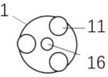
[0052] The recovery power system 16 adopts a two-way swing recovery power engine 161 , and the recovery power engine 161 is installed in the middle of two or more primary power engines 11 evenly distributed in the circumferential direction. The working mechanism of a single "double pendulum tube" recovery power engine combined with aerodynamic attitude control is as follows: (1) In the take-off section of the rocket launch, the recovery power engine 161 and the first-stage power engine 11 are started together, and the booster rocket accelerates; the rocket rises to a certain level. After the altitude, in order to reduce the ascent acceleration of the rocket, the recovery power engine 161 can be shut down in time; during the rocket ascent, the recovery power engine 161 yaw controls the pitch and yaw attitude of the rocket, and the pneumatic separation attitude c...

Embodiment 2

[0053] Example 2: A single "non-swing tube" recovery power engine is combined with aerodynamic attitude control.

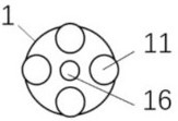
[0054] The recovery power engine 161 is installed in the middle position, and there are two or more primary power engines 11 evenly distributed in the circumferential direction of the recovery power engine 161 . During the ascent and descent of the rocket, attitude control of the rocket's pitch, yaw and roll is completed by the attitude control function of the pneumatic separation attitude control device 65 . The working mechanism of the rocket power system is as follows: (1) In the take-off section of the rocket launch, the recovery power engine 161 and the first-stage power engine 11 are started together, and the booster rocket accelerates upward; after the rocket rises to a certain height, in order to reduce the rocket's rising acceleration, the recovery power The engine 161 can be shut down in time; before the rocket is recovered and landed at a certain height...

Embodiment 3

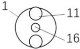
[0056] Embodiment 3: "one recovery and two main hairs", such as Figure 1A As shown, the first-stage power engine 11 adopts two engines, and a regenerative power engine is arranged in the middle. The number of two engines, two big, one small and three engines is the least, but the straight line space of the nozzles of the three engines is the largest, and the requirements for the diameter of the arrow body or the installation space of the engine are the largest; at this time, the first-level power engine or its nozzle may protrude to the first-level arrow body. Outside the arrow wall (casing), it is not conducive to the engine layout. It is less difficult to control a single regenerative power engine. Therefore, the cost of this three-engine solution is lower.


PUM


Abstract

The invention discloses a pneumatic separation recoverable carrier rocket for launching sub-orbital loads, and belongs to the technical field of spaceflight rockets, the pneumatic separation recoverable carrier rocket comprises a first-stage rocket body with a fairing at the upper end, and a first-stage power engine and a recovery power system are arranged at the lower end of the first-stage rocket body; a second-stage rocket loaded with a load is contained in the fairing, the fairing comprises a pneumatic separation attitude control device, and the pneumatic separation attitude control device comprises a gas cylinder; the gas cylinder is connected with an air cylinder used for pushing the second-stage rocket upwards, the gas cylinder is further connected with at least two gas conveying pipelines, and the gas conveying pipelines are evenly distributed in the circumferential direction of the inner wall of the fairing. The pneumatic separation attitude control device is adopted to provide separation force and adjust the attitude of the rocket, and through overall recovery of the fairing body and the first-stage rocket body, sub-orbital load non-pyrotechnic separation is achieved, auxiliary attitude control is also achieved, it is ensured that recovered power fuel sinks to the bottom and an engine works normally, and the launching cost is reduced.

Description

technical field [0001] The invention belongs to the technical field of aerospace rockets, and in particular relates to an aerodynamically separated recoverable carrier rocket for launching suborbital loads. Background technique [0002] With the continuous development of aerospace technology at home and abroad, how to reduce the cost of space launch has gradually become one of the main challenges faced by the entire aerospace industry. The demand for commercial aerospace development has put forward higher requirements for low-cost launch and low-cost rockets; especially for Some low-altitude and high-speed flight test launches, and the recovery and reuse of vehicles and their payloads are important measures to reduce costs. Since the middle of the last century, the world's aerospace powers have continued to carry out research and experiments on reusable space transportation systems. [0003] Existing reusable vehicles, such as SpaceX's "Falcon-9R" rocket, use a vertical ret...

Claims


Application Information

Patent Timeline
Patent Type & Authority Applications(China)
IPC IPC(8): F42B15/00F42B15/01F42B10/62
CPCF42B15/00F42B15/01F42B10/62Y02T50/40
Inventor 隋国发
Owner 精易兴航(北京)科技创新有限公司
Why Eureka
Try Eureka