Inductor structure and power supply circuit
A power supply circuit and inductance technology, which is applied in circuits, transformer/inductor cooling, transformer/inductor components, etc., can solve the problems of large inductance, slow branch perception, etc., and achieve fast transient response and heat dissipation Strong, Small Inductor Size Effect
- Summary
- Abstract
- Description
- Claims
- Application Information
AI Technical Summary
Problems solved by technology
Method used
Image
Examples
Embodiment 1
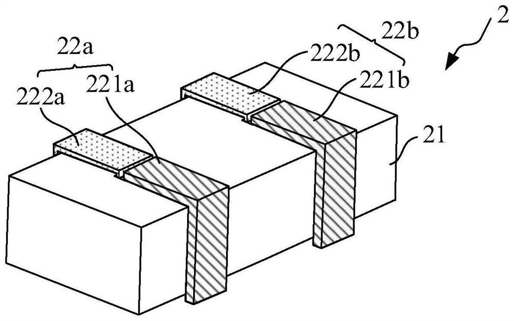
[0065] like figure 2 As shown, this embodiment provides an inductance structure 2, and the inductance structure 2 includes:
[0066] At least one magnetic core 21 and N groups of windings, each group of the windings includes a phase output coil 221 and an interphase coupling coil 222; wherein, N is a natural number greater than or equal to 2. In this embodiment, N is set to 2. In actual use, the value of N can be set as required.
[0067] like figure 2 As shown, the magnetic core 21 is used for winding coils.
[0068] Specifically, the magnetic core 21 is realized by using a magnetic powder core material. The magnetic powder core is a soft magnetic material formed by mixing and pressing ferromagnetic powder particles and an insulating medium, which itself has a much higher saturation magnetic flux density than ferrite. and lower thermal conductivity. As an example, the magnetic core 21 has a cubic structure.
[0069] It should be noted that, in actual use, the shape of th...
Embodiment 2
[0096] like Figure 8 As shown, this embodiment provides an inductance structure 2, which is different from the first embodiment in that the inductance structure 2 further includes a wire frame 25, and the phase output coil 221 and the interphase coupling coil 222 pass through the The wire rack 25 is used to fix the relative positions of the phase output coil 221 and the phase-to-phase coupling coil 222 to facilitate combined installation.
[0097] Specifically, in this embodiment, three sets of windings are taken as an example, and each set of windings is respectively located in the corresponding through hole. For the specific arrangement, please refer to Embodiment 1 and Embodiment 2, which will not be repeated here. Each group of windings is fixed in the wire frame 25 , and the relative position of each coil is determined based on each through hole. The wire frame 25 can realize the overall installation of each coil, which is convenient and quick.
[0098]More specifically...
Embodiment 3
[0102] like Figure 9 As shown, the present embodiment provides an inductor structure 2, which is different from the first and second embodiments in that the line width of the phase output coil 221 disposed outside the through hole is larger than the width of the through hole.
[0103] Specifically, in this embodiment, four sets of windings are taken as an example, and each set of windings is respectively located in the corresponding through hole. For the specific setting method, refer to the first embodiment, which will not be repeated here. The line width of each phase output coil 221 (first line segment) located inside the through hole is less than or equal to the width of the through hole. In this embodiment, the line width of each phase output coil 221 located inside the through hole is equal to the width of the through hole. The widths of the through holes are the same; the line width of each phase output coil 221 (the second line segment and / or the third line segment) l...
PUM
 Abstract
Description
Claims
Application Information
 - R&D
- Intellectual Property
- Life Sciences
- Materials
- Tech Scout
- Unparalleled Data Quality
- Higher Quality Content
- 60% Fewer Hallucinations
Browse by: Latest US Patents, China's latest patents, Technical Efficacy Thesaurus, Application Domain, Technology Topic, Popular Technical Reports.
© 2025 PatSnap. All rights reserved.Legal|Privacy policy|Modern Slavery Act Transparency Statement|Sitemap|About US| Contact US: help@patsnap.com


