Quantum dot solution injection method, light color conversion structure and light-emitting chip
A quantum dot solution and light-emitting chip technology, which is applied in the direction of electrical components, circuits, semiconductor devices, etc., can solve the problems of insufficient injection of quantum dot solution, leakage of blue light, uneven color conversion, etc., and achieve good color conversion effect and better performance Good, avoid light leakage effect
- Summary
- Abstract
- Description
- Claims
- Application Information
AI Technical Summary
Problems solved by technology
Method used
Image
Examples
Embodiment 1
[0033] This embodiment provides a quantum dot solution injection method, which is used for quantum dot injection in a light-color conversion structure, so as to convert the light emitted by the LED chip into a target light color. The light-emitting surface of the chip is provided with a light-color conversion structure, so that the blue LED chip is used to emit red light, green light, etc.
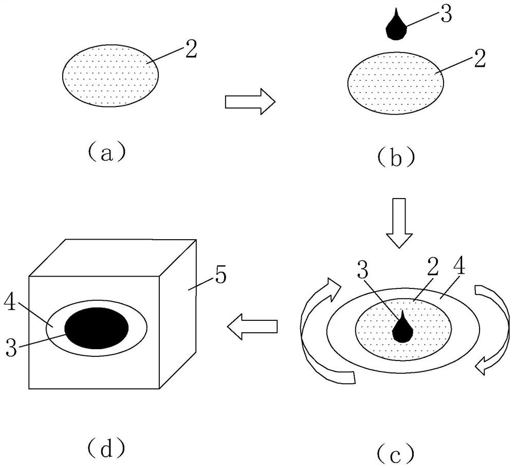
[0034] see Figure 1 to Figure 5 , the quantum dot solution injection method provided in this embodiment includes the following steps S1 to S7.
[0035] S1, providing a quantum dot solution containing quantum dots and a porous structure 2 having holes 1 for filling the quantum dot solution.
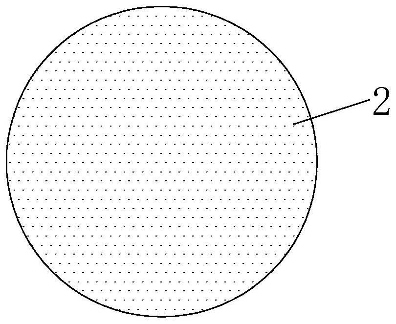
[0036] Among them, the porous structure 2 such as figure 1 , figure 2 As shown, the porous structure 2 can be a sheet-like structure with a plurality of holes 1, such as a sapphire substrate with a plurality of holes. After the quantum dot solution is injected into the holes 1 of the porous struct...
Embodiment 2
[0050] see Image 6 , which is different from the first embodiment above, in this embodiment, the sequence of vacuuming and arranging the quantum dot solution on the surface of the porous structure 2 is changed, and the above steps S4 and S5 are replaced by steps S01-S03, and the following steps are performed in sequence. Steps S01, S02, S03:
[0051] S01, put the porous structure 2 into the vacuum chamber 5, such as Image 6 As shown in (b), the vacuum is evacuated to the second vacuum degree.
[0052] S02, the quantum dot solution 3 is arranged on the surface of the porous structure 2 where the holes 1 are exposed.
[0053] S03 , maintaining the second vacuum degree for a fourth period of time, so that the hole 1 is fully injected with the quantum dot solution 3 .
[0054] In this embodiment, the quantum dot solution 3 is also dropped into the local area of the porous structure 2 where the surface of the hole 1 is exposed, and then the quantum dot solution 3 in the loca...
Embodiment 3
[0057] The difference from the first embodiment above is that in this embodiment, the above step S5 is replaced by the following steps S51-S56:
[0058] S51 , putting the porous structure 2 into the vacuum chamber, evacuating to a third degree of vacuum, and maintaining the third degree of vacuum for a fifth period of time.
[0059] S52, vent the vacuum.
[0060] S53, vacuuming again to the fourth vacuum degree, and maintaining the fourth vacuum degree for a seventh period of time.
[0061] S54, vent the vacuum.
[0062] S55 , vacuuming to the fifth vacuum degree again, and maintaining the fifth vacuum degree for an eighth time period.
[0063] S56, vent the vacuum.
[0064] Wherein, the third vacuum degree, the fourth vacuum degree, and the fifth vacuum degree may be the same, for example, less than -100kPa; the fifth, seventh, and eighth durations may be the same, for example, 4 minutes, 5 minutes . After the vacuum is released, the gas in the vacuum chamber will give t...
PUM
 Abstract
Description
Claims
Application Information
 - R&D
- Intellectual Property
- Life Sciences
- Materials
- Tech Scout
- Unparalleled Data Quality
- Higher Quality Content
- 60% Fewer Hallucinations
Browse by: Latest US Patents, China's latest patents, Technical Efficacy Thesaurus, Application Domain, Technology Topic, Popular Technical Reports.
© 2025 PatSnap. All rights reserved.Legal|Privacy policy|Modern Slavery Act Transparency Statement|Sitemap|About US| Contact US: help@patsnap.com


