Product surface ironing equipment for silk product processing and production
A technology for ironing equipment and products, applied in fabric surface trimming, textiles and papermaking, etc., can solve the problems of silk product wrinkles and poor ironing effect, achieve strong safety mechanism, improve quality and effect, and improve flat pressing effect Effect
- Summary
- Abstract
- Description
- Claims
- Application Information
AI Technical Summary
Problems solved by technology
Method used
Image

Examples
Embodiment 1
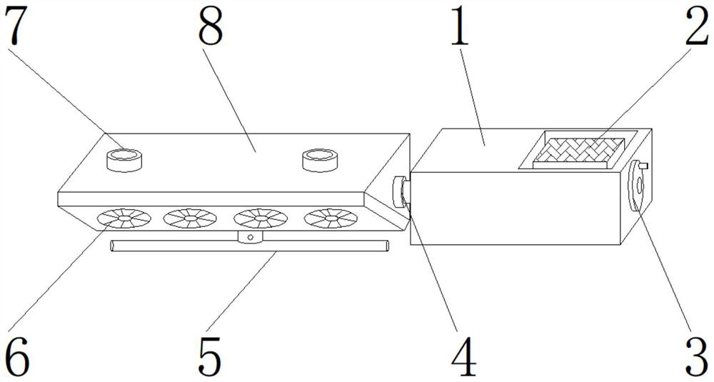
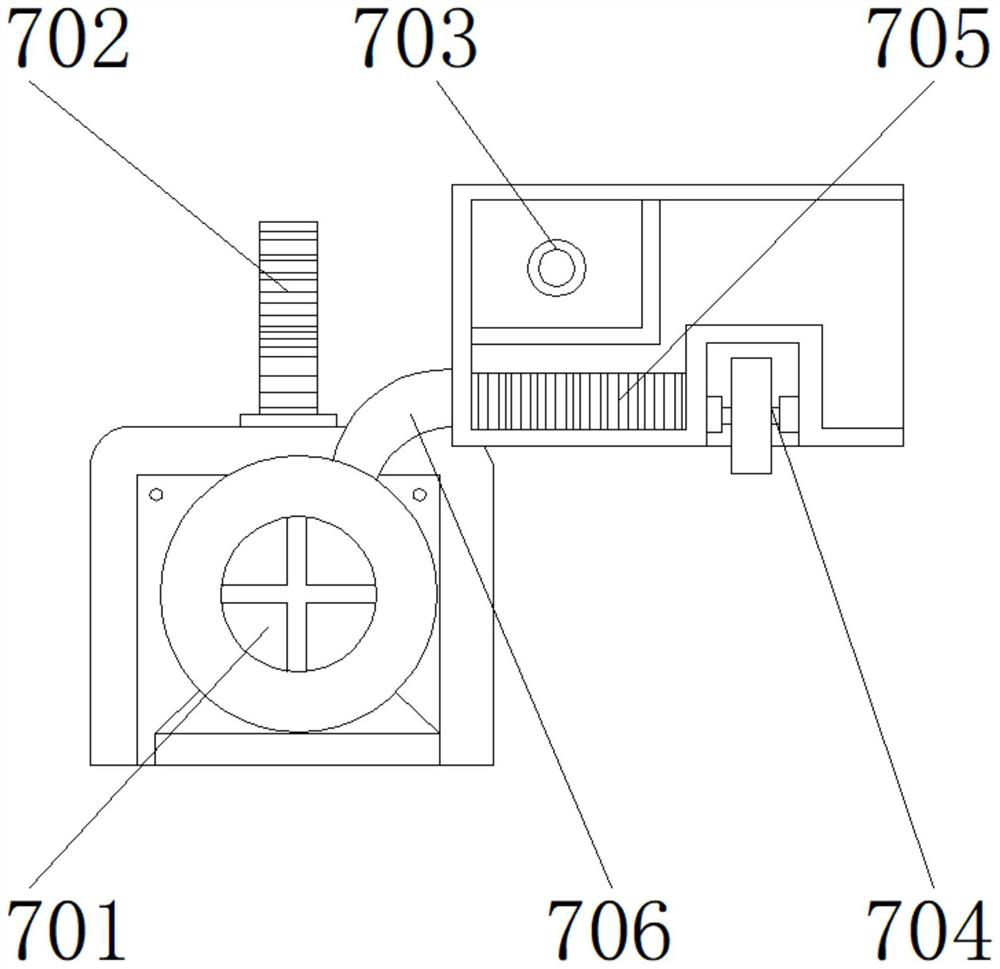
[0029] like Figure 1-6 As shown, the present invention provides a product surface ironing device for silk product processing and production, comprising a main body 1, a flat pressing device 3 is arranged on one side of the main body 1, a driving device 2 is arranged on the upper end of the main body 1, and the main body 1 The other side is provided with a connecting shaft 4, one side of the connecting shaft 4 is provided with a work box 8, the upper end of the work box 8 is provided with a steam generator 7, and the outer surface of the lower end of the work box 8 is provided with an ironing board 6 for ironing. The lower end of the plate 6 is provided with a lifting mechanism 5; the steam generating device 7 includes a steam chamber 701, an air intake hopper 702, a diffuser 703, a hydraulic device 704, a heating device 705, and an air duct 706, and the heating device 705 is located on one side of the air duct 706. , the intake hopper 702 is located at the upper end of the st...
Embodiment 2
[0032] like Figure 1-6As shown, on the basis of Embodiment 1, the present invention provides a technical solution: preferably, the air conduit 706 is located on the upper end side of the steam chamber 701, the air diffuser 703 is located at the upper end of the heating device 705, and the hydraulic device 704 is located in the heating device. side of the 705.
[0033] A notch is provided between the steam chamber 701 and the air duct 706. The lower end of the air duct 706 is detachably connected to the upper end of the steam chamber 701 through the notch. A fixing bolt is arranged between the heating device 705 and the hydraulic device 704. The heating device One side of 705 is fixedly connected to one side of the hydraulic device 704 through a fixing bolt, a welding block is provided between the air diffusion hole 703 and the heating device 705, and the lower end of the air diffusion hole 703 is fixedly connected to the upper end of the heating device 705 through the welding...
Embodiment 3
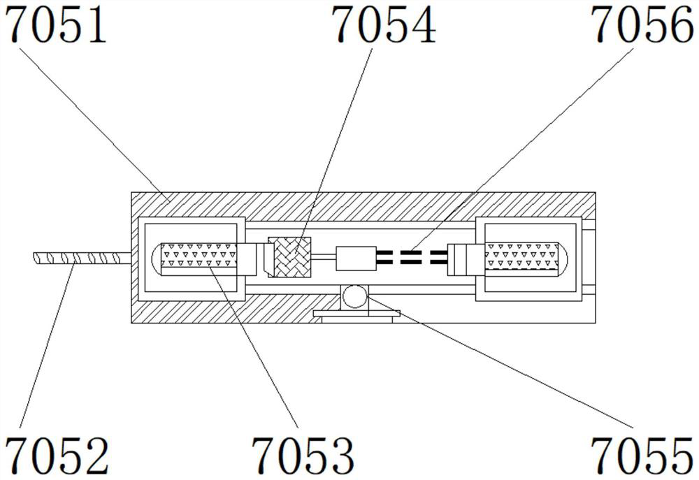
[0035] like Figure 1-6 As shown, on the basis of Embodiment 1, the present invention provides a technical solution: preferably, the heating device 705 includes a casing 7051, a heat pipe 7052, a heating pipe 7053, a refractory fiber pad 7054, a high-temperature electric heater 7055, and a heating wire 7056, the heat pipe 7052 is located on one side of the casing 7051, the heating pipe 7053 is located inside the casing 7051, the refractory fiber mat 7054 is located on one side of the heating pipe 7053, the heating wire 7056 is located on one side of the refractory fiber mat 7054, and the high-temperature electric heater 7055 Located at the lower end of the heating wire 7056.
[0036] A connection hole is provided between the shell 7051 and the heat pipe 7052, one side of the shell 7051 is fixedly connected to one side of the heat pipe 7052 through the connection hole, and a super glue is set between the heating pipe 7053 and the refractory fiber pad 7054, and the refractory fi...
PUM
 Abstract
Description
Claims
Application Information
 - Generate Ideas
- Intellectual Property
- Life Sciences
- Materials
- Tech Scout
- Unparalleled Data Quality
- Higher Quality Content
- 60% Fewer Hallucinations
Browse by: Latest US Patents, China's latest patents, Technical Efficacy Thesaurus, Application Domain, Technology Topic, Popular Technical Reports.
© 2025 PatSnap. All rights reserved.Legal|Privacy policy|Modern Slavery Act Transparency Statement|Sitemap|About US| Contact US: help@patsnap.com