Flexible contact network state monitoring system

A condition monitoring system, catenary technology, applied in transmission systems, system integration technology, measuring devices, etc., can solve the problems of complex monitoring process, high monitoring cost, inability to distinguish faults, etc., to achieve accurate monitoring results and improve inspection efficiency , the effect of good market prospects

Pending Publication Date: 2022-07-12
四川艾德瑞电气有限公司 +2
View PDF0 Cites 1 Cited by
  • Summary
  • Abstract
  • Description
  • Claims
  • Application Information

AI Technical Summary

Problems solved by technology

[0003] At present, for the electrified railway catenary, the railway line adopts regular manual inspection and regular special operation vehicle inspection to monitor the operation status of the catenary, resulting in high monitoring cost, high work intensity, complicated monitoring process, and monitoring quality. Due to issues such as the impact on the personal quality of personnel, the regular monitoring method cannot understand the status of the catenary in real time, and predict hidden failures in advance, so there is a risk of affecting the safe operation of electrified railways
In order to solve the above problems, an automatic monitoring system and monitoring method for catenary status have also appeared at present, which install acceleration or distance sensor monitoring terminals at the weight string, so as to automatically monitor whether there is a fault in the catenary system of each anchor section, and solve the problem of artificial There are problems in the inspection, but the current automatic monitoring system is a single parameter and a single power supply, such as detecting the B value through a laser or ultrasonic sensor, monitoring whether it is falling through an acceleration sensor sensor, and using a battery for power supply, etc. When a single sensor fails or In the case of a battery failure, it is impossible to tell whether there is a failure, and thus it is impossible to detect the abnormal hidden dangers of the catenary

Method used


Image

  • Flexible contact network state monitoring system

Examples


Embodiment Construction

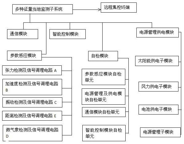
[0017] figure 1 As shown, a flexible catenary state monitoring system includes a multi-feature local monitoring subsystem and a remote centralized control terminal. The multi-feature local monitoring subsystems have the same multiple sets; each set of multi-feature local monitoring subsystems includes electrical A parameter sensing module, an intelligent control module, a communication module, a power management power supply module, a self-checking module, and multiple sets of local monitoring subsystems with multiple characteristics are respectively installed at the compensation device of the catenary anchor; the parameter sensing module includes Electrically connected tension detection and signal conditioning circuit A, acceleration detection and signal conditioning circuit B, vibration detection and signal conditioning circuit C, micro-meteorological detection and signal conditioning circuit D, distance detection and signal conditioning circuit E; the self-checking module in...


PUM


Abstract

A flexible contact network state monitoring system comprises multiple sets of same multi-characteristic-quantity local monitoring subsystems and a remote centralized control terminal. Each set of multi-characteristic-quantity local monitoring subsystem comprises a parameter sensing module, an intelligent control module, a communication module, a power management power supply module and a self-checking module which are electrically connected, and the multiple sets of multi-characteristic-quantity local monitoring subsystems are respectively installed at a compensation device of an anchor of a contact network. The system has the advantages of being convenient to install, flexible in networking, convenient to expand, more accurate in monitoring result and the like, hidden dangers and faults of the overhead line system can be accurately found after installation, maintainers are reminded to repair the overhead line system in time, and a multi-power-source redundant power supply method, a same-anchor-section monitoring information sharing method and a multi-parameter comprehensive evaluation method are adopted. And meanwhile, the state of the contact network does not need to be checked manually one by one in an anchoring manner, so that the state maintenance of the contact network is realized, the labor cost is reduced, and the checking efficiency is improved.

Description

technical field [0001] The invention relates to the field of traction power supply equipment, in particular to a flexible catenary state monitoring system. Background technique [0002] The electrified railway catenary compensation device is a general term for the compensator and its braking equipment that automatically adjust the tension of the catenary and the load-bearing cable. When the temperature changes, the leads expand or contract due to thermal expansion and contraction due to the temperature change. Because the compensators are installed at the anchors under the leads at both ends of the anchor section, under the action of the gravity of the falling mass, the tension of the leads can be automatically adjusted and the slack of the leads can be kept to meet the technical requirements, so that the stability and elasticity of the contact suspension can be obtained. In order to improve, improve the quality of catenary operation. [0003] At present, for the electrifi...

Claims


Application Information

Patent Timeline
Patent Type & Authority Applications(China)
IPC IPC(8): G01R31/08G01D21/02H04Q9/00H04L67/12
CPCG01R31/085G01D21/02H04Q9/00H04L67/12Y02E40/70
Inventor 代文平唐辉李军廖睿李煜伟杜青全王所宋务华唐良兵肖琨唐伟贺毅杨佳刘涛陈科钟源王志强阙明高保吕小龙兰培强
Owner 四川艾德瑞电气有限公司
Why Eureka
Try Eureka