Correction method of LCD strip-shaped target material assembly
A calibration method and target material technology, applied in the direction of forming tools, manufacturing tools, metal processing equipment, etc., to achieve the effect of improving calibration efficiency and high yield
- Summary
- Abstract
- Description
- Claims
- Application Information
AI Technical Summary
Problems solved by technology
Method used
Image

Examples
Embodiment 1
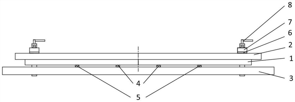
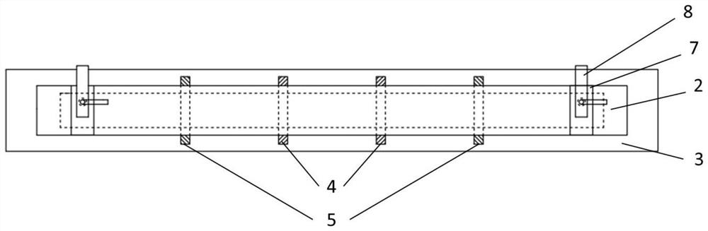
[0065]This embodiment provides a calibration method for an LCD bar-shaped target assembly, and the calibration method includes the following steps:
[0066] (1) Place the LCD strip target assembly with a temperature of 110°C flat on the calibration platform in a U shape, control the temperature of the calibration platform to be 110°C, along the length direction of the LCD strip target assembly, close to Two first spacers are arranged symmetrically inside and along the center line, and two second spacers are arranged near the end and symmetrically along the center line. Both the first spacer and the second spacer are placed on the LCD bar. between the shaped target component and the calibration platform, and the thickness of the first spacer is greater than the thickness of the second spacer;
[0067] Wherein, the target material in the LCD bar-shaped target material assembly is a titanium target material, and the back plate is a copper-chromium alloy back plate of model C18200...
Embodiment 2
[0071] This embodiment provides a calibration method for an LCD bar-shaped target assembly, and the calibration method includes the following steps:
[0072] (1) Place the LCD bar-shaped target assembly with a temperature of 100°C flat on the calibration platform in a U shape, control the temperature of the calibration platform to be 100°C, along the length direction of the LCD bar-shaped target assembly, close to Two first spacers are arranged symmetrically inside and along the center line, and two second spacers are arranged near the end and symmetrically along the center line. Both the first spacer and the second spacer are placed on the LCD bar. between the shaped target component and the calibration platform, and the thickness of the first spacer is greater than the thickness of the second spacer;
[0073] Wherein, the target material in the LCD bar-shaped target material assembly is a molybdenum target material, and the back plate is a copper-nickel-chromium alloy back p...
Embodiment 3
[0077] This embodiment provides a calibration method for an LCD bar-shaped target assembly, and the calibration method includes the following steps:
[0078] (1) Place the LCD bar-shaped target assembly with a temperature of 100°C flat on the calibration platform in a U shape, control the temperature of the calibration platform to be 100°C, along the length direction of the LCD bar-shaped target assembly, close to Two first spacers are arranged symmetrically inside and along the center line, and two second spacers are arranged near the end and symmetrically along the center line. Both the first spacer and the second spacer are placed on the LCD bar. between the shaped target component and the calibration platform, and the thickness of the first spacer is greater than the thickness of the second spacer;
[0079] Wherein, the target material in the LCD bar-shaped target material assembly is an aluminum target material, and the back plate is a copper-zinc alloy back plate of mode...
PUM
| Property | Measurement | Unit |
|---|---|---|
| Thickness | aaaaa | aaaaa |
| Width | aaaaa | aaaaa |
| Thickness | aaaaa | aaaaa |
Abstract
Description
Claims
Application Information