
Cooling device based on bionic veins

A cooling device and blade vein technology, applied in the cooling system of the power unit, the combustion of the air inlet of the power unit, etc., can solve the problems of increasing the load of the body and affecting the flight performance of the hypersonic vehicle, and achieve the purpose of increasing the degree of turbulence and the Outstanding processing technology and the effect of increasing the heat exchange area

Active Publication Date: 2022-07-15
中国空气动力研究与发展中心设备设计与测试技术研究所
View PDF18 Cites 0 Cited by
  • Summary
  • Abstract
  • Description
  • Claims
  • Application Information

AI Technical Summary

Problems solved by technology

[0003] The coolant carried by the hypersonic vehicle will greatly increase the weight of the body and affect the flight performance of the hypersonic vehicle

Method used


Image

  • Cooling device based on bionic veins
  • Cooling device based on bionic veins
  • Cooling device based on bionic veins

Examples


Embodiment 1

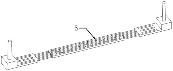
[0040] Figure 5aThree configurations of the active cooling inner flow channel 5 are given. Configuration 1 is a straight-through cooling flow channel; The adjacent main cooling flow channels 501 are not directly connected, but are connected through the branch cooling flow channels 502. The branch cooling flow channels 502 and the flow direction in the main cooling flow channel 501 form an acute angle α; configuration 3 is the second type of leaf vein bionic cooling Flow channel, on the basis of the first type of leaf vein bionic cooling flow channel, the branch cooling flow channel inlet spoiler 503 and the branch cooling flow channel outlet spoiler bump 504 are added to specify the flow direction in the main cooling flow channel 501 The direction of the branch cooling channel 502 maintained at an acute angle is the flow direction of the branch cooling channel 502. Along the inlet and outlet of the branch cooling channel 502 in the flow direction, the branch cooling channel i...


PUM


Abstract

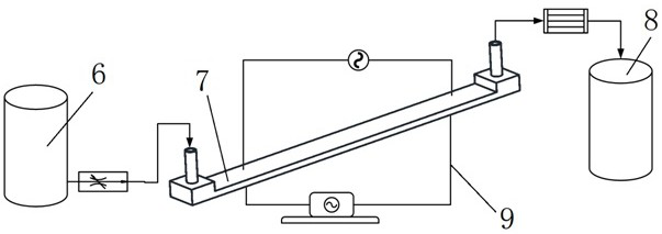
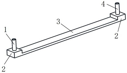
The invention belongs to the technical field of active cooling, and discloses a cooling device based on bionic veins. The cooling device comprises a fuel feeding barrel, a cooling assembly and a fuel collecting barrel which are sequentially connected from front to back, and further comprises a monitoring system. The front end and the rear end of the cooling assembly are connected with a cooling liquid inlet pipeline and a cooling liquid outlet pipeline respectively, and the middle section wraps a cold part section. An active cooling inner flow channel is arranged in the middle section and comprises main cooling flow channels which are parallel to one another, and the main cooling flow channels are communicated through branch vein cooling flow channels. The main cooling flow channels are separated through intermittent partitions, the cross section of each intermittent partition is in the shape of an isosceles trapezoid with a short upper bottom edge and a long lower bottom edge and an isosceles trapezoid with a long upper bottom edge and a short lower bottom edge which are arranged alternately, and the adjacent main cooling flow channels are in the shape of isosceles trapezoids arranged in a staggered mode. According to the cooling device, fuel carried by the hypersonic aircraft is adopted as a coolant, the temperature of a cold using part section is effectively reduced, and the cooling efficiency of an engine active cooling structure and the thermal safety of an engine structure are improved.

Description

technical field [0001] The invention belongs to the technical field of active cooling, and in particular relates to a cooling device based on bionic leaf veins. Background technique [0002] During the high-speed flight of a hypersonic vehicle, the high-speed flow of airflow will bring a huge thermal burden to the hypersonic vehicle. At present, the thermal protection schemes of hypersonic vehicles are mainly divided into active thermal protection, semi-active thermal protection and passive thermal protection. Three categories. Convective cooling technology in active thermal protection technology has received extensive attention in recent years, one of which is active cooling. Active cooling removes most of the heat through coolant. [0003] The coolant carried by the hypersonic vehicle will greatly increase the weight of the body and affect the flight performance of the hypersonic vehicle. In recent years, research has found that using the fuel that comes with the body a...

Claims


Application Information

Patent Timeline
IPC IPC(8): B64D33/02B64D33/08
CPCB64D33/02B64D33/08B64D2033/024
Inventor 麻越垠马斌冯松张伟聂旭涛陈万华
Owner 中国空气动力研究与发展中心设备设计与测试技术研究所
Learn More