Knee joint model capable of demonstrating pressure change in knee joint cavity in KOAPT movement

A knee joint and internal pressure technology, applied in the field of demonstrable medical models, can solve the problems of decreased curative effect, subjective discomfort of the knee joint, short follow-up time, etc., and achieve the effect of accurate pressure changes

Pending Publication Date: 2022-07-15
WUHAN FL MEDICAL TECH CO LTD
View PDF0 Cites 0 Cited by
  • Summary
  • Abstract
  • Description
  • Claims
  • Application Information

AI Technical Summary

Problems solved by technology

For example: artificial joint replacement surgery has quick results, but patients often suffer from subjective discomfort of the knee joint after surgery, coupled with osteoporosis in the elderly, they are prone to periprosthetic fractures, and there is also the problem of difficult recovery after surgery; Arthroscopic treatment has small wounds and is easy to recover, but there is a possibility of re-exacerbation in the later stage; intra-articular injection of sodium hyaluronate in non-surgical treatment is often an adjuvant treatment plan, which can cure the disease in a very short period of time. By improving the internal environment of the knee joint, it relieves symptoms and slows down the development of the disease. In the early stage, there is a good therapeutic effect, but with the gradual development of the disease, its curative effect will decline; although intra-articular injection of PRP in the treatment of KOA has achieved It has a certain curative effect, but th

Method used


Image

  • Knee joint model capable of demonstrating pressure change in knee joint cavity in KOAPT movement
  • Knee joint model capable of demonstrating pressure change in knee joint cavity in KOAPT movement
  • Knee joint model capable of demonstrating pressure change in knee joint cavity in KOAPT movement

Examples


Embodiment 1

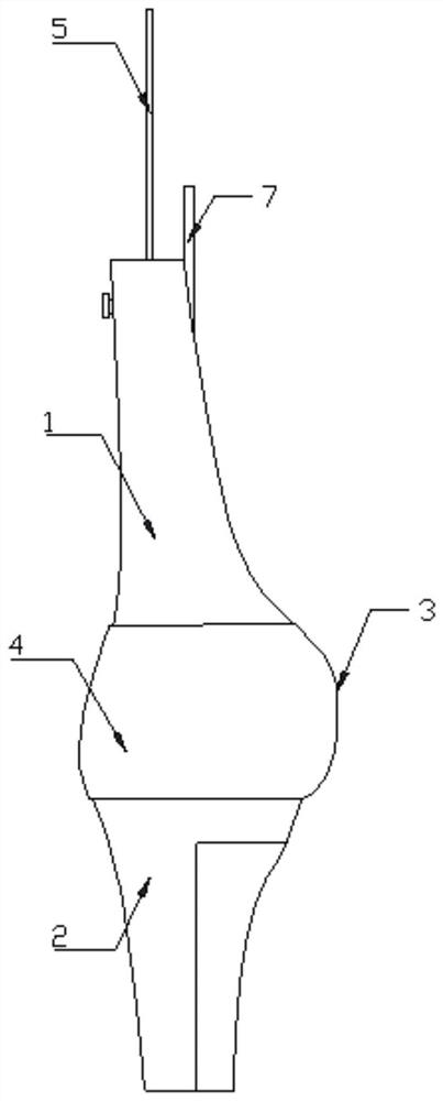
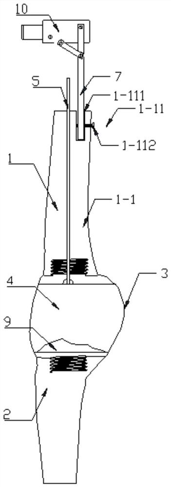
[0047] like Figures 1 to 4 As shown, the knee joint model proposed by the present invention that can demonstrate the pressure change in the knee joint cavity during KOAPT movement includes a femoral structure 1 and a tibial structure 2. The upper part of the femoral structure 1 is provided with a fixing mechanism 1-11 for connecting the swing arm 7; The middle and lower part of the tibial structure 2 is provided with a cavity 2-21 for filling the weight 6; an elastic film 3 for simulating the synovial membrane of the knee joint is sealed and connected between the femoral structure 1 and the tibial structure 2, and the elastic film 3 is wrapped inside to form a sealed integrity. There is a communication tube 5 embedded in the femoral structure 1, and the bottom end of the communication tube 5 penetrates to the bottom end of the femoral structure 1 for injecting artificial synovial fluid into the knee joint cavity 4, and the top of the communication tube 5 penetrates out of the ...

Embodiment 2

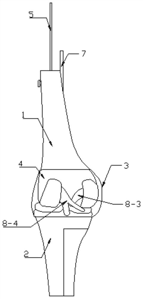
[0074]The main difference between this embodiment and Embodiment 1 is that this embodiment further includes a ligament 8, and the ligament 8 includes a patellar ligament 8-1 fixed between the upper femoral structure 1-1 and the lower tibial structure 2-2. Collateral ligament 8-2, and anterior cruciate ligament 8-3, posterior cruciate ligament 8-4 fixed between lower femoral structure 1-2 and upper tibial structure 2-1; the patellar ligament 8-1 and medial collateral ligament 8 -2 are fixed by the first ligament fixing screw holes 1-13 on the surrounding wall of the upper femoral structure 1-1, the fourth ligament fixing screw holes 2-23 on the surrounding wall of the lower tibial structure 2-2, and screws; Both the anterior cruciate ligament 8-3 and the posterior cruciate ligament 8-4 pass through the second ligament fixing screw holes 1-23 arranged on the surrounding wall of the lower femoral structure 1-2, and the third ligament on the surrounding wall of the upper tibial str...


PUM


Abstract

The invention discloses a knee joint model capable of demonstrating pressure change in a knee joint cavity in KOAPT movement. The model comprises a thighbone structure and a tibia structure, the thighbone structure comprises an upper thighbone structure and a lower thighbone structure which are vertically and hermetically connected, and a communicating pipe is embedded in the thighbone structure; the tibia structure comprises an upper tibia structure and a lower tibia structure which are hermetically connected up and down; a cylindrical elastic film which is used for simulating a knee joint synovial membrane and is provided with openings at two ends is sleeved between the lower thighbone structure and the upper tibia structure in a sealing manner, so that a completely sealed knee joint cavity is formed in the elastic film; artificial synovial fluid is injected into the communicating pipe into the knee joint cavity, the thighbone structure is swung, knee pain inducing movement is demonstrated, and the pressure change in the knee joint cavity is detected through the pressure meter connected with the top end of the communicating pipe. According to the invention, the blank that various knee joint models do not simulate the knee joint cavity and synovial fluid is filled up, and the pressure change in the joint cavity during knee pain inducing movement is clearly and intuitively demonstrated.

Description

technical field [0001] The invention belongs to the technical field of demonstrable medical models, and specifically refers to a model that can demonstrate the pressure change in the knee joint cavity during KOAPT movement. Background technique [0002] Knee osteoarthritis (KOA) is an all-round, multi-layered and varying degree of inflammation with the degenerative changes of knee cartilage as the core, often involving the bone and including the synovium, joint capsule and other structures of the joint. Sterile, chronic, progressive disease of the joints. With the intensification of population aging in modern society, the incidence of KOA is increasing year by year. According to an epidemiological survey in my country, the prevalence of KOA in people aged 60-75 is 50%, and the incidence in people over 75 is as high as 80%. Patients with KOA are often disabled due to pain and limited walking activities, and the ultimate disability rate is 53%. Pain, as the most important s...

Claims


Application Information

Patent Timeline
IPC IPC(8): G09B23/32G09B23/34
CPCG09B23/32G09B23/34
Inventor 刘昕婷余兰宋九宏
Owner WUHAN FL MEDICAL TECH CO LTD
Why Eureka
Try Eureka