Integrated device for manually or automatically short-circuiting leakage ampere meter

A leakage current and short-circuit technology, applied in the field of integrated devices, can solve the problems of laboriousness, unreliable grounding, affecting the operation speed, etc., to solve the hidden danger of replacement, simplify the replacement method, and ensure the effect of normal operation.

Active Publication Date: 2022-07-15
STATE GRID ZHEJIANG ELECTRIC POWER CO LTD JINHUA POWER SUPPLY CO
View PDF6 Cites 0 Cited by
  • Summary
  • Abstract
  • Description
  • Claims
  • Application Information

AI Technical Summary

Problems solved by technology

[0003] At present, the replacement of the leakage current meter in the substation adopts the method of shorting the grounding wire or the shorting method of the security wire. When the shorting method of the grounding wire is used, it is necessary to unlock the grounding end of a nearby grounding wire and install the grounding wire. There are many replacement tools. , Handling is time-consuming and labor-intensive, and the unlocking operation process is cumbersome; using the security wire short connection method, it is necessary to find a grounding point near the leakage current meter to be replaced to install the security wire grounding end, and install the conductor end vertically, which is difficult to find the grounding point. Unreliable, unstable and other issues pose a great threat to the personal safety of operation and maintenance personnel, and the existing leakage current meter is connected and fixed by bolts. It is time-consuming and laborious to remove and install the meter, and there are corrosion problems, which further affect the operation. speed

Method used


Image

  • Integrated device for manually or automatically short-circuiting leakage ampere meter
  • Integrated device for manually or automatically short-circuiting leakage ampere meter
  • Integrated device for manually or automatically short-circuiting leakage ampere meter

Examples


Embodiment Construction

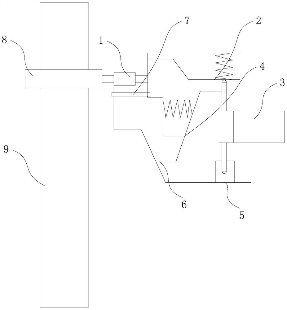
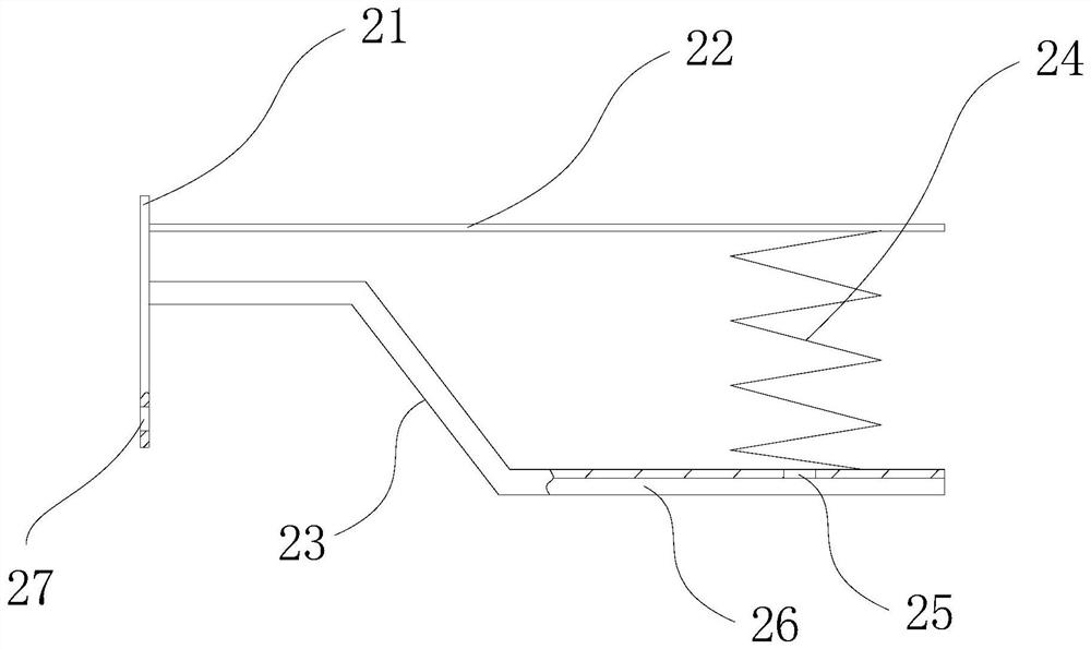
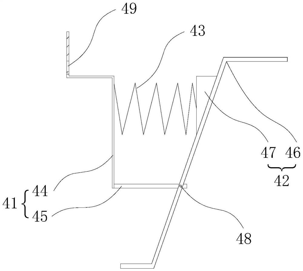
[0024] like figure 1 , figure 2 , image 3 , Figure 4 and Figure 5 As shown in the figure, an integrated device for manual or automatic short-circuit leakage ammeter, applied to the arrester, includes an insulator 1, an upper conductor assembly 2, a leakage ammeter 3, a movable grounding conductor assembly 4, a lower grounding assembly 5 and a hoop 8, The upper end of the leakage ammeter 3 is connected to the upper conductor assembly 2, the lower end of the leakage ammeter 3 is connected to the lower grounding assembly 5, and the movable grounding conductor assembly 4 is connected to the upper conductor assembly 2 through bolts. When the leakage ammeter operates normally, One end of the movable grounding conductor assembly 4 is in contact with the upper end of the leakage ammeter 3, and a movable gap 6 is provided between the other end of the movable grounding conductor assembly 4 and the lower grounding assembly 5. When the leakage ammeter 3 is automatically short-circu...


PUM


Abstract

The invention relates to an integrated device for manually or automatically short-circuiting a leakage ammeter, which comprises an insulator, an upper-end conductor assembly, the leakage ammeter, a movable grounding conductor assembly, a lower-end grounding assembly and a hoop. The movable grounding conductor assembly moves to trigger the other end of the movable grounding conductor assembly to be in contact with the lower end grounding assembly, and a manual grounding bolt is arranged between the upper end conductor assembly and the lower end grounding assembly; the leakage current meter has the advantages that the upper end conductor assembly and the lower end grounding assembly are connected through the movable grounding conductor assembly or the manual grounding bolt, the replacement mode of the meter of the leakage current meter can be greatly simplified, different requirements are met, if the movable grounding conductor assembly breaks down, short circuit can be achieved through the manual grounding bolt, and the leakage current meter is convenient to use. The problem of potential safety hazards in replacement of the leakage current meter is well solved, the safety risk of workers is greatly reduced, time and labor are saved, and normal work of the leakage current meter can be met.

Description

technical field [0001] The invention relates to an integrated device for manual or automatic short-circuit leakage current meter. Background technique [0002] The arrester is a device that protects the equipment in the substation from lightning shock waves and limits the operating overvoltage. It is an important device to ensure the safe and stable operation of the power system. A large number of arrester leakage ammeters are installed in the substation, and the insulation of the arrester valve plate is monitored through the value of the arrester leakage ammeter. , and then judge whether the arrester is in normal operation. Due to air humidity, contamination, marking process and other reasons, the leakage ammeter often appears water vapor, the dial is blurred, and the pointer falls off. At this time, the abnormal leakage ammeter needs to be replaced. [0003] At present, the replacement of leakage ammeters in substations adopts the method of shorting the grounding wire or t...

Claims


Application Information

Patent Timeline
Patent Type & Authority Applications(China)
IPC IPC(8): H02G13/00
CPCH02G13/40H02G13/20H02G13/80
Inventor 李一鸣梁勋萍周锦盛慧李丹东俞一峰龚小雪潘宏伟陆路汤益飞杜晟炜明岩张赛凡陈伟杰田志平王鹏姜妮
Owner STATE GRID ZHEJIANG ELECTRIC POWER CO LTD JINHUA POWER SUPPLY CO
Why Eureka
Try Eureka