
Photoresist removing method

A technology of photoresist and photoresist layer, which is applied in the field of semiconductors, can solve the problems of low semiconductor production efficiency and achieve the effect of improving production efficiency

Pending Publication Date: 2022-07-19
INST OF MICROELECTRONICS CHINESE ACAD OF SCI +1
View PDF0 Cites 0 Cited by
  • Summary
  • Abstract
  • Description
  • Claims
  • Application Information

AI Technical Summary

Problems solved by technology

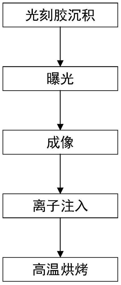
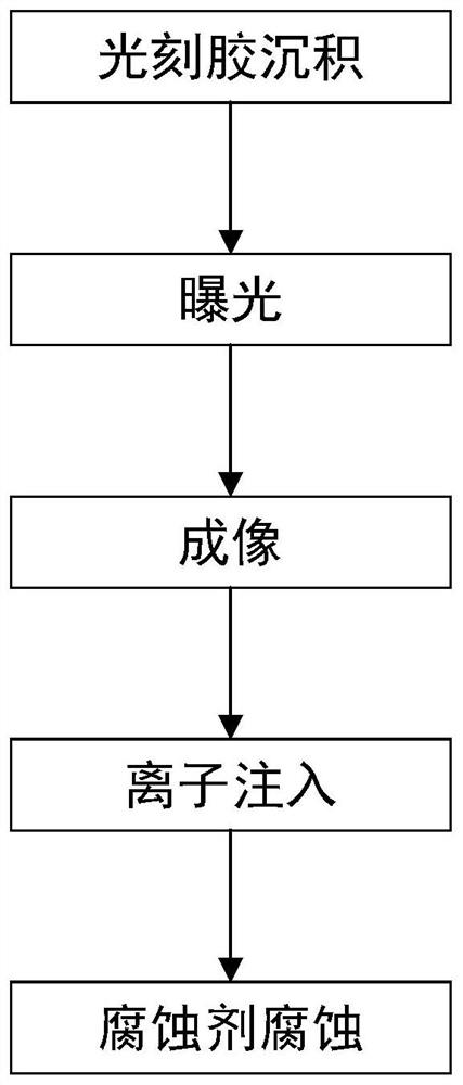
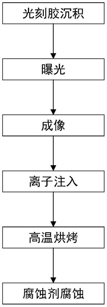
[0003] The purpose of the present invention is to provide a photoresist removal method to solve the technical problem that the photoresist layer removal process in the prior art leads to low semiconductor production efficiency

Method used


Image

  • Photoresist removing method
  • Photoresist removing method
  • Photoresist removing method

Examples


Embodiment Construction

[0018] The technical solutions of the present invention will be clearly and completely described below with reference to the accompanying drawings. Obviously, the described embodiments are a part of the embodiments of the present invention, but not all of the embodiments. Based on the embodiments of the present invention, all other embodiments obtained by those of ordinary skill in the art without creative efforts shall fall within the protection scope of the present invention.

[0019] In the description of the present invention, it should be noted that the terms "center", "upper", "lower", "left", "right", "vertical", "horizontal", "inner", "outer", etc. The indicated orientation or positional relationship is based on the orientation or positional relationship shown in the accompanying drawings, which is only for the convenience of describing the present invention and simplifying the description, rather than indicating or implying that the indicated device or element must hav...


PUM


Abstract

The invention provides a photoresist removal method, which relates to the technical field of semiconductors and comprises the following steps: providing a substrate; depositing, exposing and developing photoresist on the substrate to form a patterned photoresist layer; performing an ion implantation process and / or an etching process on the substrate; and finally, removing the photoresist layer in a high-temperature baking mode and / or a diluent corrosion mode. According to the technical scheme, compared with an existing removal method, the photoresist removal method has the advantages that the mode of removing the photoresist layer by using an ashing method or a wet removal process in the etching and cleaning stages is mainly abandoned, and the photoresist layer is directly removed in the photoetching equipment, so that the preparation efficiency of a semiconductor is effectively improved.

Description

technical field [0001] The present invention relates to the field of semiconductor technology, in particular to a method for removing photoresist. Background technique [0002] Photoresist is often used in semiconductor manufacturing processes. In the photolithography process, patterning is formed on the photoresist layer after exposure and development of the photoresist. In order to successfully carry out the subsequent film deposition process, it must be The photoresist layer is removed. In the prior art, the removal of the photoresist layer is usually performed by an ashing method and a wet removal process. However, these two removal methods are generally performed in an etching process, which leads to low semiconductor fabrication efficiency. SUMMARY OF THE INVENTION [0003] The purpose of the present invention is to provide a photoresist removal method, so as to solve the technical problem of low semiconductor manufacturing efficiency caused by the photoresist layer...

Claims


Application Information

Patent Timeline
Patent Type & Authority Applications(China)
IPC IPC(8): G03F7/42
CPCG03F7/42
Inventor 南兑浩李大烨丁明正贺晓彬刘强刘金彪周娜
Owner INST OF MICROELECTRONICS CHINESE ACAD OF SCI
Learn More