Corrosive liquid dilution equipment for biotechnology

A biotechnology and corrosive technology, which is applied in the field of corrosive liquid dilution equipment for biotechnology, can solve the problems of liquid damage to the skin and waste of manpower, and achieve the effect of automatically spraying alkaline liquid

Pending Publication Date: 2022-07-22
宋菊兰
View PDF0 Cites 0 Cited by
  • Summary
  • Abstract
  • Description
  • Claims
  • Application Information

AI Technical Summary

Problems solved by technology

[0004] In order to overcome the disadvantages of easily splashing liquid and hurting people's skin during the manual experiment, and wasting manpower by manual stirring, the technical problem to be solved is to provide a corrosive liquid dilution for biotechnology that can realize automatic stirring and dilution and has protective functions. equipment

Method used


Image

  • Corrosive liquid dilution equipment for biotechnology
  • Corrosive liquid dilution equipment for biotechnology
  • Corrosive liquid dilution equipment for biotechnology

Examples


Embodiment 1

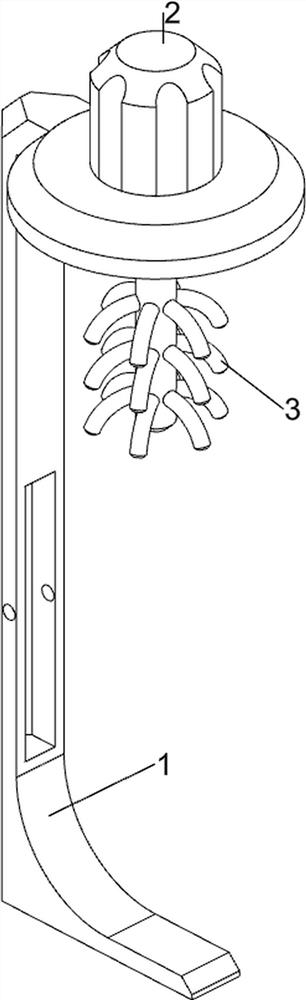
[0027] A biotechnology dilution device with corrosive liquids, such as Figure 1-4 As shown, it includes a support base 1, a cylinder 2, a stirrer 3, a clamping mechanism 4 and a protection mechanism 5. The upper part of the support base 1 is provided with a cylinder 2, the lower part of the telescopic rod of the cylinder 2 is provided with an agitator 3, and the support base 1 is provided with an agitator 3. There is a clamping mechanism 4 , and a protective mechanism 5 is provided on the support base 1 .

[0028] The clamping mechanism 4 includes a rotating rod 40 , a mounting plate 41 , a clamping device 42 , a clamping tooth 43 and a first clamping rod 44 . The left and right sides of the mounting plate 41 are slidably connected with clamps 42, the inner wall of the clamp 42 is evenly provided with clamping teeth 43, and the left clamp 42 is connected with a first clamp 44 on both the front and rear sides of the right part , the right side of the clamping device 42 is pro...

Embodiment 2

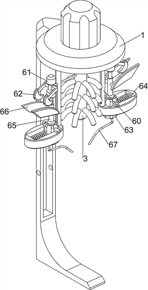
[0032] On the basis of Example 1, as figure 1 and Figure 5-9 As shown, it also includes a liquid injection mechanism 6, which includes a slide rail 60, a descending column 61, an arc-shaped plate 62, a liquid storage box 63, a first spring 64, a piston 65, a moving plate 66 and a water outlet pipe 67 , the left and right sides of the bottom wall of the upper part of the support base 1 are connected with slide rails 60, and a descending column 61 is slidably connected between the slide rails 60. The telescopic rod of the cylinder 2 is connected with the descending column 61. A curved plate 62 is connected, the lower part of the slide rail 60 is slidably connected with a liquid storage box 63, a first spring 64 is provided between the outer side of the liquid storage box 63 and the slide rail 60 on the same side, and the liquid storage box 63 slides inside The piston 65 is connected with a piston 65. The piston 65 is composed of a straight rod, a sliding rod and a spring. The ...


PUM


Abstract

The invention relates to dilution equipment, in particular to corrosive liquid dilution equipment for biotechnology. The technical problem to be solved is to provide the corrosive liquid dilution equipment for the biotechnology, which can realize automatic stirring and dilution and has a protection function. According to the technical scheme, the corrosive liquid diluting equipment for the biotechnology comprises a supporting base, an air cylinder, a stirrer, a clamping mechanism and a protection mechanism, the air cylinder is arranged on the upper portion of the supporting base, the stirrer is arranged on the lower portion of an air cylinder telescopic rod, the clamping mechanism is arranged on the supporting base, and the protection mechanism is arranged on the supporting base. Through cooperation between the clamping mechanism and the protection mechanism, when the corrosive liquid is diluted, the glass container can be clamped and limited, so that the situation that the dilution effect is affected due to the fact that the glass container shifts in the process of diluting the corrosive liquid is avoided.

Description

technical field [0001] The invention relates to a dilution device, in particular to a corrosive liquid dilution device for biotechnology. Background technique [0002] In the field of biotechnology, the work of diluting corrosive liquids will be involved. Under the requirements of the experiment, the corrosion strength of the corrosive liquid needs to be reduced, and then the reduced corrosive liquid is tested. Corrosive products include sulfuric acid, nitric acid, hydrochloric acid, hydrobromic acid, hydroiodic acid and perchloric acid, etc. To reduce the corrosiveness of corrosive liquids, alkaline liquids can be added, which can be controlled according to the required corrosiveness. Add the amount of alkaline liquid. [0003] Usually, the acidic liquid is poured into the container, and then the alkaline liquid is quantitatively poured into the container. At the same time, the liquid is stirred with a stirrer to make the alkaline and acidic liquid react. During the operat...

Claims


Application Information

Patent Timeline
Patent Type & Authority Applications(China)
IPC IPC(8): B01F23/40B01F27/808B01F35/32B01F27/90B01F35/71B01F35/75B01F35/51B01F35/60B01F35/53
Inventor 宋菊兰
Owner 宋菊兰
Why Eureka
Try Eureka