Bearing trolley, assembling and conveying equipment, underground mine car assembly line and operation method of underground mine car assembly line
A technology for carrying trolleys and supporting brackets, applied in the directions of assembly machines, conveyors, mechanical conveyors, etc., can solve the problems of low efficiency and production safety in production mode, prevent collision and installation waiting, improve assembly efficiency, and prevent force dumping Effect
- Summary
- Abstract
- Description
- Claims
- Application Information
AI Technical Summary
Problems solved by technology
Method used
Image
Examples
Embodiment 1
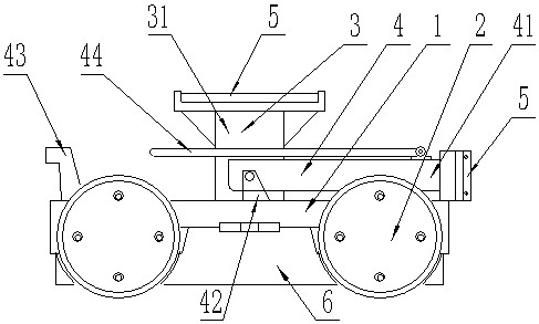
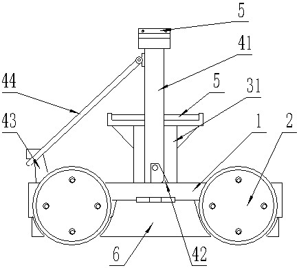
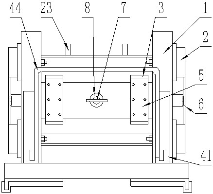
[0049] refer to figure 1 , is a schematic structural diagram of Embodiment 1 of the present invention, a carrying trolley, which is characterized in that it includes:
[0050] carriage 1;
[0051] Track wheel 2, the two sides of the two ends of the carriage 1 are respectively connected to the track wheel 2 in rotation;
[0052] A support frame one 3, the support frame one 3 is detachably connected to the center of the upper surface of the carriage 1;
[0053] The second support frame 4, the second support frame 4 is detachably connected to the center position of the upper surface of the carriage 1;
[0054] The positioning part is detachably connected in the carriage 1 .
[0055] In actual use: connected with the positioning part by the dragging device, the positioning part drives the carriage 1 to slide through the track wheel 2, and moves through the supporting frame 1 3 or the supporting frame 2 4 to carry the articles or the main body to be assembled, and move through d...
Embodiment 2
[0058] refer to Figure 1-4 , the difference of this embodiment is that: the support surfaces of the first support frame 3 and the support frame two 4 are detachably connected with a cushion block 5 .
[0059] In actual use: the frame or the engine is mounted on the support frame 1 3 and the support frame 2 4, and the pad 5 can prevent hard contact with the frame or the engine, causing collision damage when moving.
Embodiment 3
[0061] refer to Figure 4 , the difference of this embodiment is that: the top end of the support frame 1 3 has a pair of inwardly inclined outriggers.
[0062] In actual use: the support frame 1 3 has inwardly inclined outriggers, which can support the engine or non-planar structure through the inclined outriggers, which can effectively support, and there will be no single side not in contact with the engine, resulting in inconvenience. Stable support.
PUM
 Abstract
Description
Claims
Application Information
 - R&D
- Intellectual Property
- Life Sciences
- Materials
- Tech Scout
- Unparalleled Data Quality
- Higher Quality Content
- 60% Fewer Hallucinations
Browse by: Latest US Patents, China's latest patents, Technical Efficacy Thesaurus, Application Domain, Technology Topic, Popular Technical Reports.
© 2025 PatSnap. All rights reserved.Legal|Privacy policy|Modern Slavery Act Transparency Statement|Sitemap|About US| Contact US: help@patsnap.com


