Automatic film cutting machine for food packaging box processing
A food packaging box and film cutting machine technology, which is applied in the directions of packaging, transportation and packaging, container manufacturing machinery, etc., can solve the problems of film pulling, tearing, the film cannot be fitted, and exposed to the air, etc., and can reduce the length of the film. Effect
- Summary
- Abstract
- Description
- Claims
- Application Information
AI Technical Summary
Problems solved by technology
Method used
Image
Examples
Embodiment 1
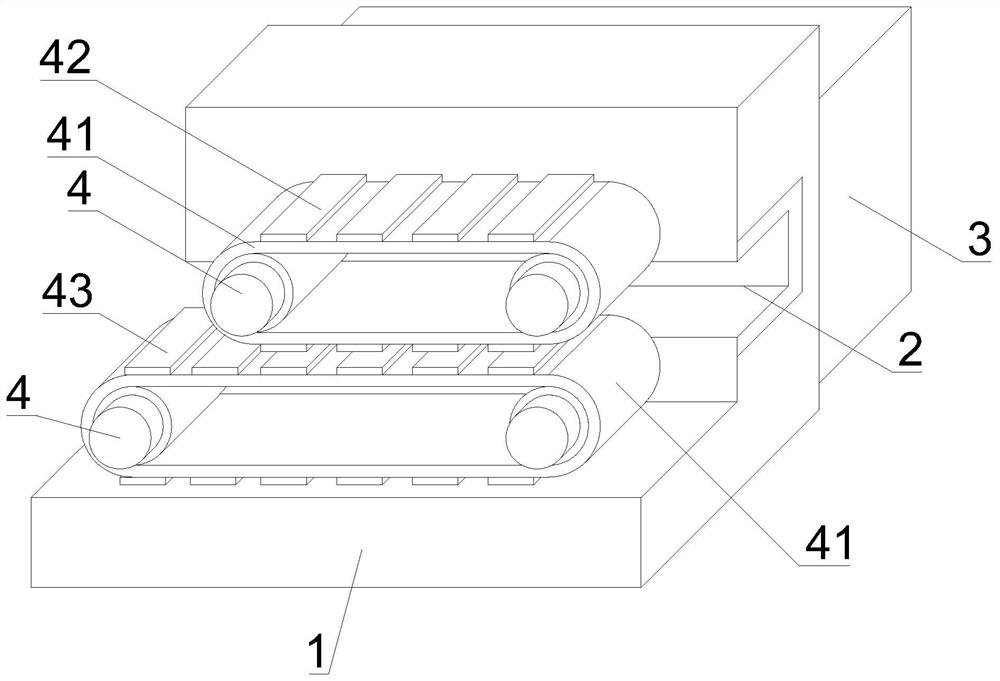
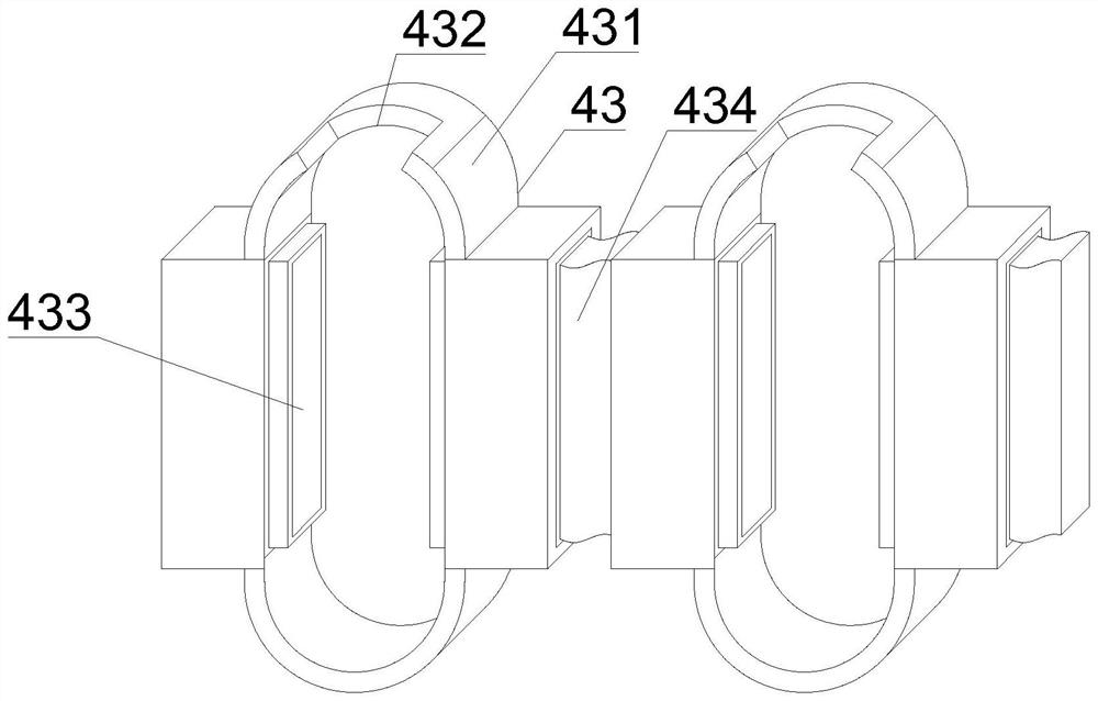
[0044] like Figure 1-7 As shown, the present invention provides an automatic film cutting machine for food packaging box processing, including a film cutting processing table 1, a cutter 2, a waste collection box 3 and a rotator 4, and the front surface of the film cutting processing table 1 can be A cutter 2 is detachably installed, a waste collection box 3 is detachably installed on the back of the film-cutting processing table 1, and a rotator 4 is detachably installed on the front of the film-cutting processing table 1, and the rotator 4 includes a food storage tank 43. The cutter 2 includes a C-type snap-fit sleeve 21, and an extruded heat-resistant elastic plate 22 is detachably connected to the inner bottom and outer surface of the C-type snap-fit sleeve 21, and the telescopic cutter 23 is detachably installed on the A suction port 24 is provided on the top outer surface of the C-type snap socket 21 and the inner surface of the C-type snap socket 21 .
[0045] In ...
Embodiment 2
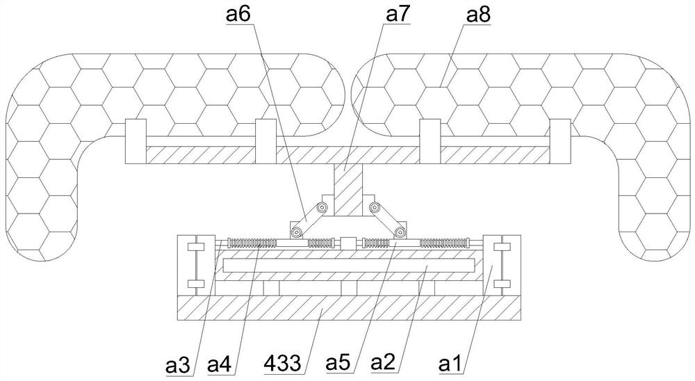
[0047] like Figure 1-7 As shown, on the basis of Embodiment 1, the present invention provides a technical solution: preferably, the outer surface of the output end of the rotator 4 is movably lapped with conveying crawler belts 41, the number of conveying crawler belts 41 is two, and the bottom A food storage groove 43 is detachably installed on the outer surface of the conveyor crawler 41, and the extrusion exhaust strip 42 is detachably installed on the outer surface of the top conveyor crawler 41. The cutter 2 includes a telescopic cutter 23 and a telescopic cutter 23. A pusher 231 is detachably mounted on the top outer surface of the pusher 231, and the output end of the pusher 231 extends to the top inner surface of the telescopic cutter 23. A cutting blade 233 is detachably connected to the top inner surface of the position sleeve 232, and a connection limit plate 1 234 is detachably connected to the outer surfaces of the two sides of the limit sleeve 232, and the outer...
Embodiment 3
[0050] like Figure 1-7 As shown, on the basis of Embodiment 1, the present invention provides a technical solution: preferably, a collector box c1 is detachably installed inside the ironing edge sealer 235, and the top inner surface of the ironing edge sealer 235 is detachably installed. The upper detachable connection is provided with an elastic wire c2, one end of the elastic wire c2 is detachably connected with a lap block c3, and an ironing block c4 is detachably installed on the lower surface of the lap block c3, and the lap block c3 The conductive posts c5 are detachably connected on the edges of the top two sides of the ironing edge sealer 235, and the snapping sleeves c6 are detachably connected on the top two edges of the ironing edge sealer 235. The top inner surface of the snapping sleeves c6 The power transmission block c7 is detachably connected, and the outer surface of the clamping sleeve c6 is movably overlapped with the outer surface of the conductive column ...
PUM
 Abstract
Description
Claims
Application Information
 - R&D
- Intellectual Property
- Life Sciences
- Materials
- Tech Scout
- Unparalleled Data Quality
- Higher Quality Content
- 60% Fewer Hallucinations
Browse by: Latest US Patents, China's latest patents, Technical Efficacy Thesaurus, Application Domain, Technology Topic, Popular Technical Reports.
© 2025 PatSnap. All rights reserved.Legal|Privacy policy|Modern Slavery Act Transparency Statement|Sitemap|About US| Contact US: help@patsnap.com


