Flexible guide piece, flexible guide mechanism and flexible guide device

A technology of flexible guiding mechanism and guiding parts, which is applied in the direction of measuring devices, mechanical equipment, force/torque/work measuring instruments, etc., which can solve the problems of large vibration, easy bending, and small bending stiffness, so as to achieve force balance and prevent Effect of eccentric vibration and high bending rigidity

Pending Publication Date: 2022-07-22
FOSHAN HUADAO SUPER PRECISION TECH CO LTD
View PDF0 Cites 0 Cited by
  • Summary
  • Abstract
  • Description
  • Claims
  • Application Information

AI Technical Summary

Problems solved by technology

[0003] Existing flexible guiding mechanisms mainly include springs and flexible hinge mechanisms. The spring stroke is long, but the bending stiffness is small. Usually, it needs to cooperate with the guiding mechanism to realize the function of buffering and guiding. In addition, since the spring is helically wound by a single wire , the force is transmitted through the spring wire, so when the force is applied to the end of the spring, when the spring stroke is long, the spring is easily bent when the force deviates from the central axis of the spiral; and it is easy to generate large vibration when working at high frequency

Method used


Image

  • Flexible guide piece, flexible guide mechanism and flexible guide device
  • Flexible guide piece, flexible guide mechanism and flexible guide device
  • Flexible guide piece, flexible guide mechanism and flexible guide device

Examples


Embodiment 1

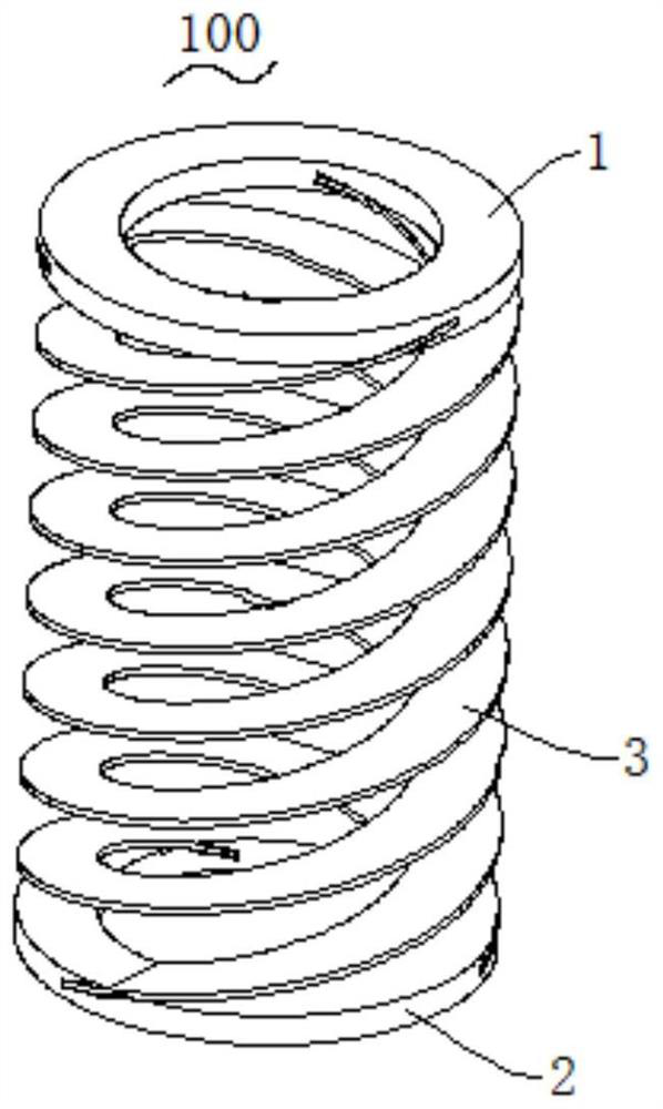
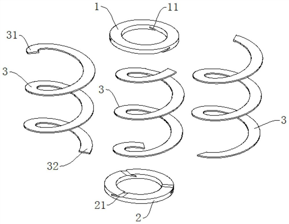
[0036] combine Figure 1 to Figure 2 As shown, this embodiment provides a flexible guide member, and the flexible guide member is provided with a plurality of spiral bodies 3 between the first fixed seat 1 and the second fixed seat 2. Each helix 3 is composed of helixes 3 of the same structure. The inner diameter, outer diameter, pitch, helix direction and other structural parameters of the three helixes 3 are the same. During installation, the three helixes 3 can be superimposed coaxially together. That is, the three helical central axes of the three helical bodies 3 are coaxially arranged, and then the three first end heads 31 at one end of the three helical bodies 3 are fastened with the first fixing seat 1, and the three second end heads at the other end are fastened. 32 is fastened with the second fixing seat 2, so as to form such as figure 1 Flexible guide shown.

[0037] Further, in order to make the three spiral bodies 3 evenly bear the load force applied to the firs...

Embodiment 2

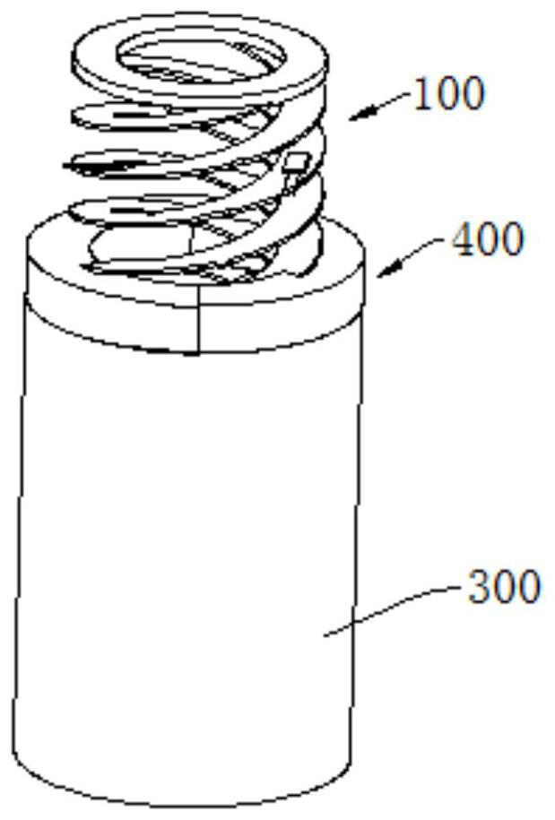
[0043] combine Figure 3 to Figure 7 As shown, this embodiment provides a flexible guide mechanism, the flexible guide mechanism includes the flexible guide member 100 in the above-mentioned embodiment, and the adjustment adjustment that is fastened to the lower end of the flexible guide member 100 and the lower bottom surface of the second fixed seat 2 The seat 200, the adjustment sleeve 300 sleeved on the adjustment seat 200 and connected with the adjustment seat 200 in a threaded connection, and an adjustment ring disposed on the upper end of the adjustment sleeve 300 and connected with the flexible guide member 100 in a threaded connection, the adjustment ring 400 and the adjustment sleeve 300 are coaxially tightened. solid.

[0044] Further, due to the influence of the first fixing base 1 and the second fixing base 2 at both ends of the flexible guide member 100, the adjusting ring 400 cannot form a threaded connection with the first fixing base 1 and the second fixing ba...

Embodiment 3

[0047] combine Figure 8 As shown, this embodiment provides a flexible guide device. Since the cross-section of the spiral body 3 of the flexible guide member 100 in the flexible guide device adopts a rectangular cross-section with a high aspect ratio, it can be directly connected to each flexible guide member 100. A strain measurement sensor is installed on the spiral body 3, and then the plurality of strain measurement sensors 500 are electrically connected to the external electronic control device, so as to obtain the force condition of the plurality of flexible guide members 100 in real time, and then calculate the flexible guide through the external electronic control device. The axial moment and bending moment received by the member 100 can further effectively monitor the application of the flexible guide member 100, so that the flexible guide member 100 can play a better guiding and buffering role.

[0048] The specific circuit settings of the external electronic contro...


PUM


Abstract

The invention belongs to the technical field of flexible guide mechanisms, and discloses a flexible guide part which is high in flexural rigidity and stable and reliable in structure and has good buffering and guiding functions. In addition, the multiple first end heads and the multiple second end heads are evenly distributed around the spiral central axis in the circumferential direction, so that stress on the multiple spiral bodies is more balanced, and the problems of eccentric vibration and the like caused by uneven stress on the flexible guide part are effectively solved. The invention further provides a flexible guide mechanism, the flexible guide mechanism can conveniently and flexibly adjust the number of effective stress turns of the spiral body in the flexible guide piece through the arrangement of the adjusting sleeve and the adjusting ring, and therefore rigidity adjustment of the flexible guide piece is achieved, and the use requirements under different buffering and guide working conditions are met.

Description

technical field [0001] The present invention relates to the technical field of flexible guide mechanisms, in particular to a flexible guide member, a flexible guide mechanism and a flexible guide device. Background technique [0002] The flexible guiding mechanism is widely used in precision displacement, precision force control and flexible buffering because it has better buffering and guiding functions and is not easy to generate friction. [0003] The existing flexible guide mechanisms mainly include springs and flexible hinge mechanisms. The springs have a long stroke, but their bending stiffness is small. Usually, they also need to cooperate with the guide mechanism to realize the buffering and guiding function. In addition, since the spring is spirally wound by a single wire , the force is transmitted through the spring wire, so when the force is applied to the end of the spring, when the spring stroke is long, the spring is easily bent when the force deviates from the...

Claims


Application Information

Patent Timeline
Patent Type & Authority Applications(China)
IPC IPC(8): F16F1/12F16F1/06G01L5/00
CPCF16F1/121F16F1/123F16F1/042F16F1/06G01L5/00
Inventor 杨志军张春衡白有盾
Owner FOSHAN HUADAO SUPER PRECISION TECH CO LTD
Why Eureka
Try Eureka