
Continuous rotation detonation ramjet engine capable of supplying oil and gas in radial direction

A ramjet and detonation technology, applied in the field of aero-engines, can solve the problems of non-adjustable fuel injection hole diameter, unstable pressure operating temperature, violation of compact engine layout and lightweight design, etc. Achieve stable work and good blending effect

Inactive Publication Date: 2022-07-22
清航空天(北京)科技有限公司
View PDF6 Cites 0 Cited by
  • Summary
  • Abstract
  • Description
  • Claims
  • Application Information

AI Technical Summary

Problems solved by technology

However, whether it is air film cooling or water cooling, additional cooling medium, pipelines and accessories are required, which is contrary to the compact layout and lightweight design of the engine required by cutting-edge technology
[0004] The current research on the continuous rotation detonation engine has achieved more results and accumulated more experience, but the fuel injection hole diameter of the current detonation combustion chamber is not adjustable, and the pressure is unstable. The working temperature of the combustion chamber is too high, exceeding 1500K. Generally, stainless steel materials cannot work for a long time, and the diameter of the fuel injection hole cannot be adjusted. Different sizes of injection holes require different parts to be processed correspondingly.

Method used


Image

  • Continuous rotation detonation ramjet engine capable of supplying oil and gas in radial direction
  • Continuous rotation detonation ramjet engine capable of supplying oil and gas in radial direction
  • Continuous rotation detonation ramjet engine capable of supplying oil and gas in radial direction

Examples


Embodiment Construction

[0024] The present invention will be described in further detail below in conjunction with the accompanying drawings and examples, but it should be noted that these embodiments do not limit the present invention. Effective transformations or substitutions fall within the protection scope of the present invention.

[0025] In the description of the embodiments of the present invention, it should be understood that the terms "center", "portrait", "horizontal", "upper", "lower", "front", "rear", "left" and "right" , "vertical", "horizontal", "top", "bottom", "inside", "outside", etc. indicate the orientation or positional relationship based on the orientation or positional relationship shown in the accompanying drawings, only for the convenience of describing this The invention creates and simplifies the description, rather than indicating or implying that the device or element referred to must have a specific orientation, be constructed and operate in a specific orientation, and...


PUM


Abstract

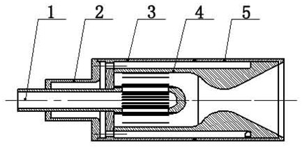
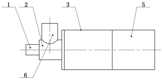
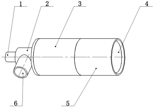
The invention provides a continuous rotation detonation ramjet engine capable of supplying oil and gas in the radial direction, and belongs to the technical field of aero-engines, the continuous rotation detonation ramjet engine comprises an oxidant injection mandrel used for oxidant inflow, a fuel pressure stabilization cavity used for fuel pressure stabilization and a combustion chamber, and a pressure stabilization space is formed in the oxidant injection mandrel; a plurality of first gaps are evenly distributed in the oxidizing agent injection mandrel, oxidizing agents enter the combustion chamber through the first gaps, and a plurality of second gaps used for introducing fuel into the combustion chamber are evenly distributed in the radial direction of the fuel pressure stabilizing cavity. According to the ramjet engine, the feeding direction of fuel is changed into the radial direction, so that the fuel and an oxidizing agent are subjected to radial hedging in the combustion chamber, and good mixing is achieved; the oxidant and the fuel cavity are respectively provided with a pressure stabilizing structure, and gap flow channels which are uniformly distributed at 360 degrees also play a role in flow equalization; and the combustion chamber is self-cooled by adopting fuel required by the combustion chamber, so that stable work of the detonation combustion chamber in a long-time detonation state is realized, and the problem of long-time reliable work of the detonation ramjet engine is solved.

Description

technical field [0001] The invention belongs to the technical field of aero-engines, and in particular relates to a continuous rotary detonation ramjet engine for radially supplying oil and gas. Background technique [0002] The competition in the aerospace field is becoming more and more fierce, and the research on key innovative technologies in the aerospace field has attracted more and more attention from various countries. In recent years, with the continuous deepening of research on hypersonic vehicles and single-stage orbiting power systems, new continuous rotating detonation engine technology has been rapidly developed. Studies have shown that the propulsion technology based on detonation combustion can greatly reduce fuel consumption and greatly improve the specific impulse characteristics of the power plant. meaning. As a leading technology that can overtake on a curve, its comprehensive and in-depth research is more urgent. [0003] The continuous rotary detonat...

Claims


Application Information

Patent Timeline
Patent Type & Authority Applications(China)
IPC IPC(8): F23R7/00F02K7/18
CPCF23R7/00F02K7/18
Inventor 高宗永董琨刘海洋王琳赵学松曹鑫彪
Owner 清航空天(北京)科技有限公司
Learn More