Pluggable photovoltaic protection circuit breaker
A kind of protection circuit breaker, plug-in technology, applied in circuit breaker parts, protection switch operation/release mechanism, protection switch distinction marking and other directions, can solve the problems of prone to errors, complicated secondary wiring of photovoltaic protection circuit breakers, etc. Simplify wiring, realize intelligent remote management, and reduce the volume of the cabinet
- Summary
- Abstract
- Description
- Claims
- Application Information
AI Technical Summary
Problems solved by technology
Method used
Image
Examples
Embodiment 1
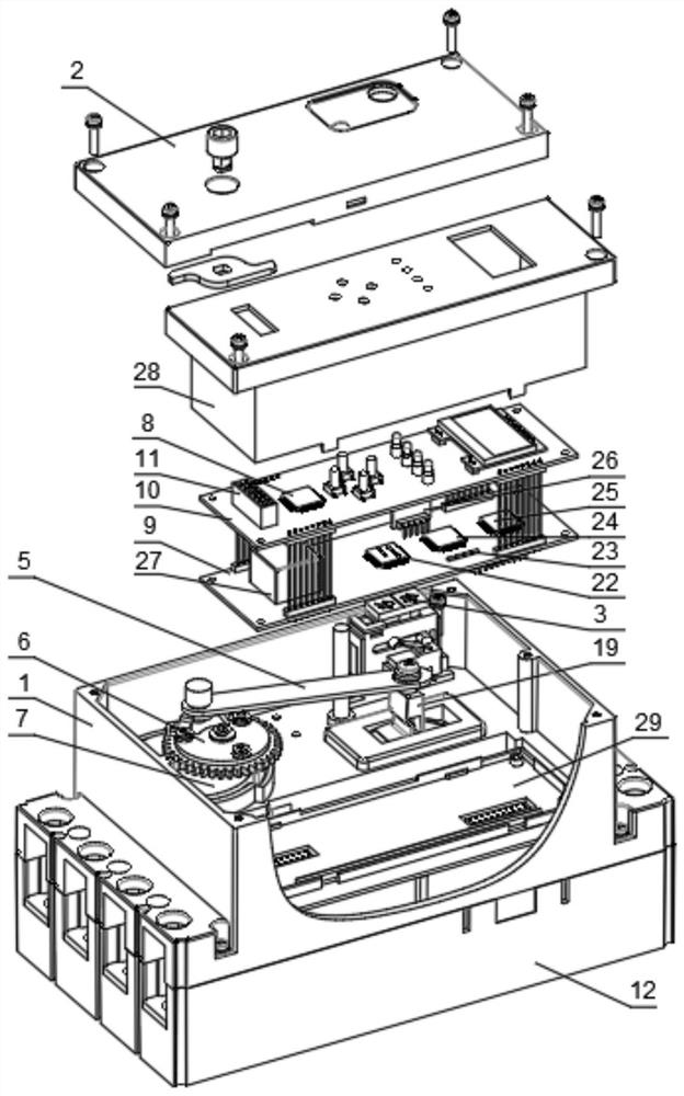
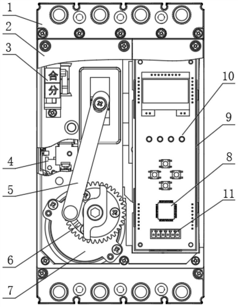
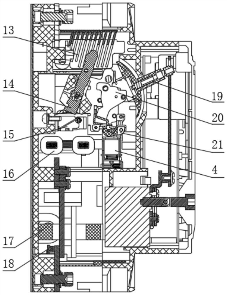
[0024] like Figure 1-3 As shown, a pluggable photovoltaic protection circuit breaker proposed by the present invention includes a middle cover 1, an opening and closing indicator 3, a release 4 and a base 12. The middle cover 1 is fixed with a surface cover 2 by bolts. And the inside of the middle cover 1 is fixed with a motor 7 by bolts, the output end of the motor 7 is fixed with a cam 6, the cam 6 is eccentrically rotated and connected with a connecting rod 5, the base 12 is fixed on the lower part of the middle cover 1, and the base 12 is installed with a Arc extinguishing system 13, contact system 14, electromagnetic system 15, current transformer 16, zero sequence transformer 17, temperature sensor 18, handle 19, transmission part 20 and drawbar 21, the temperature sensor 18 model adopts BRW600-400A, the main The control board 9 includes a storage module 22, a protection control circuit module 23, a data processing module 24, a metering module 25, a Bluetooth module 26 ...
Embodiment 2
[0027] like figure 1 As shown in the figure, a pluggable photovoltaic protection circuit breaker proposed by the present invention, compared with the first embodiment, the present embodiment also includes a power inlet wire arranged at the bottom of the base 12 , and the power inlet wire is electrically connected to the main control board 9 . connected, and the voltage of the incoming line is 220V, the inside of the control module cover 28 is fixed with a key display board 10 by bolts, the key display board 10 is welded with an LED display screen by solder, and the LED display screen is clamped with the control module cover 28. The key display board 10 is soldered with a main control board 9 and a communication module 11. The mode of the communication module 11 is RS-485. One side of the main control board 9 is fixed with an HPLC carrier module 8, which supports short-range wireless and local maintenance. HPLC The carrier module 8 adopts a modular and pluggable design. The cir...
Embodiment 3
[0030] like Figure 1-3As shown in the figure, a pluggable photovoltaic protection circuit breaker proposed by the present invention, compared with Embodiment 1 or Embodiment 2, this embodiment further includes that the outer surface of the opening and closing indicator 3 is provided with an opening and closing label, The opening and closing label is inserted into the through hole of the cover 2, one end of the connecting rod 5 is provided with an opening, and a positioning pin is set in the movable sleeve in the opening, and the positioning pin is threadedly connected with the cam 6. In the middle of the electromagnetic system 15, and the contacts of the contact system 14 are located inside the arc extinguishing system 13, the transmission mechanism 20 is located in the middle of the handle 19 and the drawbar 21, and the transmission mechanism 20 and the drawbar 21 are connected to the base 12 through bolts Connection, the handle 19 is slidingly connected with the lever 20 of...
PUM
 Abstract
Description
Claims
Application Information
 - R&D
- Intellectual Property
- Life Sciences
- Materials
- Tech Scout
- Unparalleled Data Quality
- Higher Quality Content
- 60% Fewer Hallucinations
Browse by: Latest US Patents, China's latest patents, Technical Efficacy Thesaurus, Application Domain, Technology Topic, Popular Technical Reports.
© 2025 PatSnap. All rights reserved.Legal|Privacy policy|Modern Slavery Act Transparency Statement|Sitemap|About US| Contact US: help@patsnap.com


