Transceiving circuit applied to B-mode ultrasound

A technology of a transceiver circuit and a receiving circuit, which is applied in the field of transceiver circuits used in B ultrasound, can solve the problem of high power consumption, and achieve the effects of reducing power consumption, reducing parasitic capacitance, improving speed and sampling accuracy

Pending Publication Date: 2022-07-22
成都川为生物医疗科技有限责任公司
View PDF7 Cites 0 Cited by
  • Summary
  • Abstract
  • Description
  • Claims
  • Application Information

AI Technical Summary

Problems solved by technology

The transceiver circuit in the existing B-ultrasound system (livestock and poultry B-ultrasound detection equipment) is a discrete device solution, and the power consumption is relatively high

Method used


Image

  • Transceiving circuit applied to B-mode ultrasound
  • Transceiving circuit applied to B-mode ultrasound
  • Transceiving circuit applied to B-mode ultrasound

Examples


Embodiment Construction

[0018] The following will be combined with the Figure 1-Figure 3 The present invention is described in detail, and the technical solutions in the embodiments of the present invention are clearly and completely described. Obviously, the described embodiments are only a part of the embodiments of the present invention, rather than all the embodiments. Based on the embodiments of the present invention, all other embodiments obtained by those of ordinary skill in the art without creative efforts shall fall within the protection scope of the present invention.

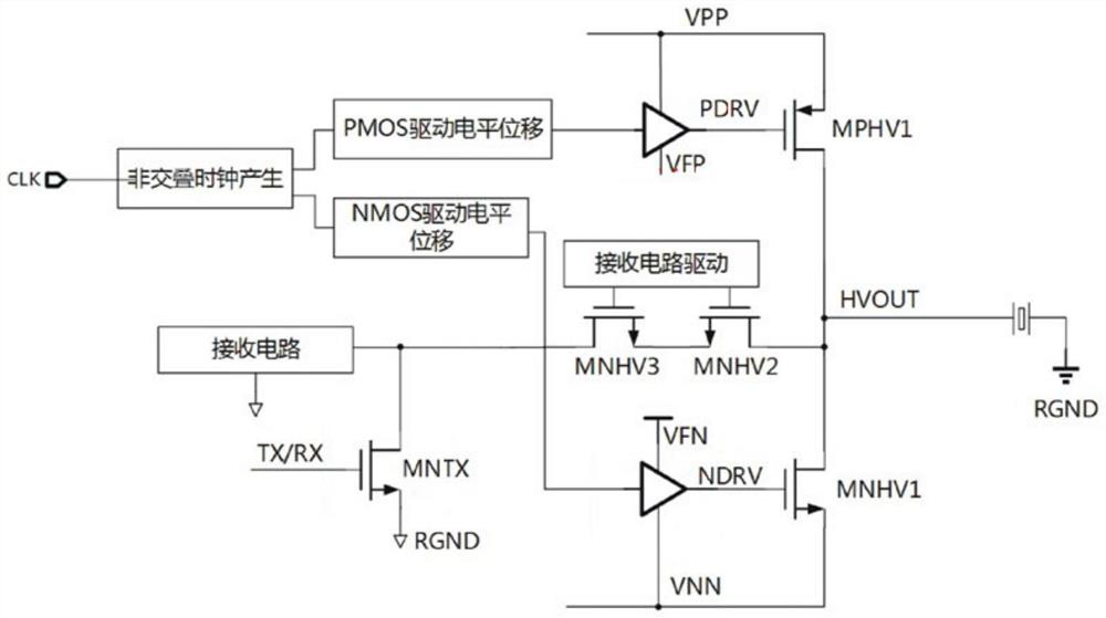
[0019] The present invention provides a transceiver circuit applied to B ultrasound by improving; such as Figure 2-Figure 3 shown, can be implemented as follows;

[0020] The main part of the invention has only four high-voltage MOSFETs, namely MPHV1, MNHV1, MNHV2, and MNHV3, which greatly saves the system complexity and effectively reduces the chip cost.

[0021] At the same time, since the voltage sources of the drivi...


PUM


Abstract

The invention discloses a transmit-receive circuit applied to B-mode ultrasound. The circuit belongs to a low-cost, multi-path and high-voltage transceiver circuit applied to B-mode ultrasound. According to the circuit, a high-voltage floating switch is used for driving a load, a common device is used as a receiving circuit, time-sharing control of TX and RX is achieved through optimized time sequence control, and meanwhile a receiving protection circuit is integrated. According to the scheme, the cost is greatly reduced, and the parasitic capacitance of each node is greatly reduced, so that the speed and the sampling precision are improved, and the power consumption is reduced.

Description

technical field [0001] The invention relates to the technical field related to B-ultrasound detection equipment for livestock and poultry, and in particular to a transceiver circuit applied to B-ultrasound. Background technique [0002] In the B-ultrasound system (livestock and poultry B-ultrasound detection equipment), the transceiver circuits are generally driven separately. like figure 1 As shown, it includes a logic control and signal processing unit, a transmitting circuit, a high-voltage switch array, an ultrasonic transducer, a receiving circuit clamp, and a receiving circuit. The logic and signal processing part is responsible for controlling the sending and receiving circuits and sampling the received signal. The TX circuit is responsible for sending positive and negative pulses. The high-voltage switch array is responsible for opening the channels that need to be sampled and closing the sampling channels that are not needed. The ultrasonic transducer is respons...

Claims


Application Information

Patent Timeline
Patent Type & Authority Applications(China)
IPC IPC(8): H04B1/40H04B1/401H03K19/0185A61B8/00
CPCH04B1/40H04B1/401H03K19/018507A61B8/56A61B2503/40
Inventor 刘显军
Owner 成都川为生物医疗科技有限责任公司
Why Eureka
Try Eureka