
Bedrock mark stability monitoring system

A monitoring system and bedrock mark technology, applied in the field of bedrock mark and land subsidence monitoring, can solve the problems of construction influence, large volume, low range, etc., and achieve the effects of little influence by temperature difference, low system complexity and high sensitivity

Active Publication Date: 2022-07-26
CHINA WATER RESOURCES BEIFANG INVESTIGATION DESIGN & RES
View PDF5 Cites 0 Cited by
  • Summary
  • Abstract
  • Description
  • Claims
  • Application Information

AI Technical Summary

Problems solved by technology

[0004] The stability of bedrock marks buried in stable bedrock is better than that of ordinary buried rocks, but there are also certain instability phenomena. For example, shallow bedrock marks may still be affected by the groundwater level. The influence of hardness and construction, the sub-mark sinking after cutting the bedrock, has an impact on the stability of the main mark, etc. Generally, after the bedrock mark is established, long-term observation is required to verify its stability
[0005] The stability monitoring of bedrock marks is mainly based on precision leveling survey, but the joint precision leveling survey is mainly to verify the actual elevation, which takes a long time and consumes a lot of manpower, so it cannot be continuously observed
At present, the principle of static leveling has been used to monitor the stability of the bedrock mark by using a liquid level or differential pressure static level. For example, the bedrock mark of Tianjin Liqizhuang uses a liquid level static level to monitor the stability of the bedrock mark , the bedrock mark in the Haihe River Basin is monitored by a differential pressure static level. The former has higher precision, but the range is lower. After exceeding the range, it needs to be re-calibrated, which will introduce errors, and the volume is large. There is a certain influence, and it is generally used for short-range monitoring; the latter has a large range, but its accuracy is relatively high, and it is mostly used for remote monitoring

Method used


Image

  • Bedrock mark stability monitoring system
  • Bedrock mark stability monitoring system

Examples


Embodiment Construction

[0032] The technical solutions in the embodiments of the present invention will be clearly and completely described below with reference to the accompanying drawings in the embodiments of the present invention; obviously, the described embodiments are only a part of the embodiments of the present invention, not all of the embodiments. The embodiments of the present invention, and all other embodiments obtained by those of ordinary skill in the art without creative work, fall within the protection scope of the present invention.

[0033] In the description of the present invention, it should be noted that the orientations or positional relationships indicated by the terms "upper", "lower", "inner", "outer", "top / bottom", etc. are based on the orientations shown in the accompanying drawings Or the positional relationship is only for the convenience of describing the present invention and simplifying the description, rather than indicating or implying that the referred device or e...


PUM


Abstract

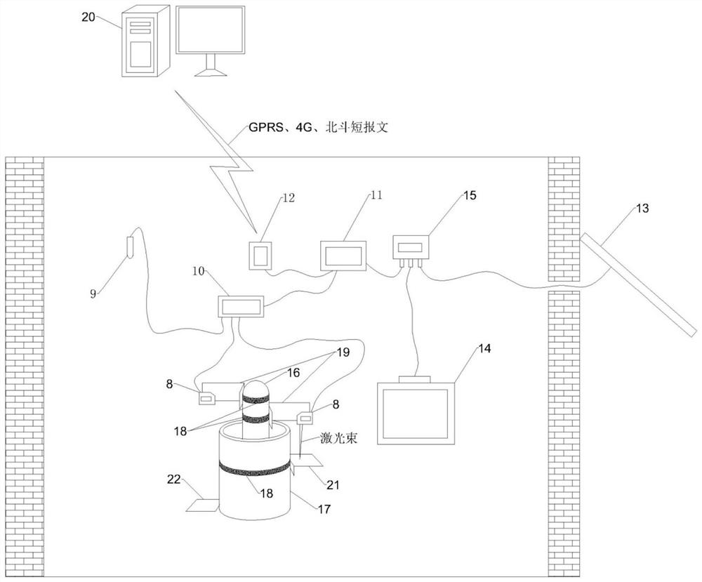
The invention discloses a bedrock mark stability monitoring system which comprises a sensing system, an acquisition, analysis and transmission system, a power supply system, a bedrock mark, a fixing system, a display system and a light reflecting system. The device can replace a static force level gauge monitoring system to be used for monitoring bedrock mark stability and ground subsidence, adopts the laser displacement sensor for distance measurement, has the advantages of small size, high sensitivity, small influence by temperature difference and large measuring range compared with a liquid surface type static force level gauge, has the advantages of high precision, low system complexity and the like compared with a pressure difference type static force level gauge, and is suitable for popularization and application. The system has a remote communication function and can display the bedrock mark state and the land subsidence condition in real time.

Description

technical field [0001] The invention relates to the field of bedrock marker and ground subsidence monitoring, in particular to a bedrock marker stability monitoring system. Background technique [0002] Bedrock markers are generally buried on stable bedrock as a leveling base point, and their main uses include leveling and geological change observation, such as providing elevation levels for large-scale engineering construction and seismic observations. [0003] The bedrock mark is mainly composed of two parts: the main mark and the auxiliary mark. The main mark is used as a benchmark, and the auxiliary mark is also called the wall protection pipe, which mainly plays the role of protecting the main mark. According to the depth of buried bedrock, bedrock marks can be divided into shallow marks and deep marks. Shallow marks mostly refer to bedrock marks buried within tens of meters on shallow bedrock, and deep marks refer to buried depths of more than 100 meters or even For t...

Claims


Application Information

Patent Timeline
Patent Type & Authority Applications(China)
IPC IPC(8): G01C5/00G01B11/02G01S17/08
CPCG01C5/00G01B11/02G01S17/08
Inventor 刘满杰谢津平郭林刘海瑞徐寅生何力劲柳志会谢兆龙王雪娇陈凯
Owner CHINA WATER RESOURCES BEIFANG INVESTIGATION DESIGN & RES
Learn More