Method and device for controllable steering of pressure conduction at head end of medical nasal feeding catheter
A catheter head and end pressure technology, applied in the direction of therapeutic feeding tubes, catheters, etc., can solve problems such as laborious, patient vomiting, bending, etc., and achieve the effect of strong controllability and convenient operation
- Summary
- Abstract
- Description
- Claims
- Application Information
AI Technical Summary
Problems solved by technology
Method used
Image
Examples
Embodiment 1
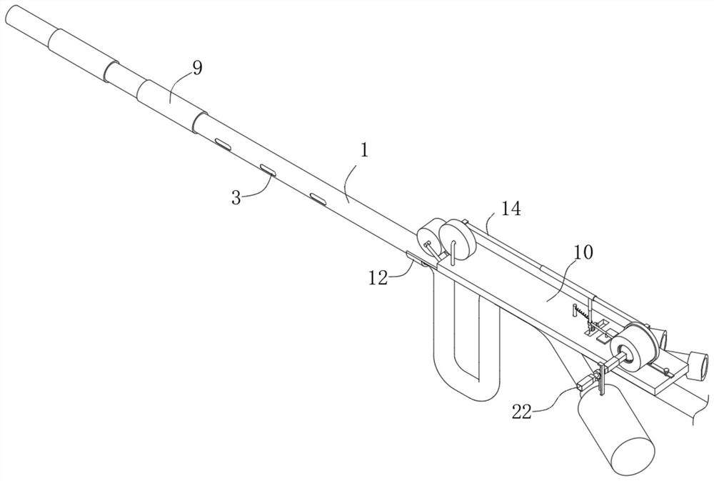
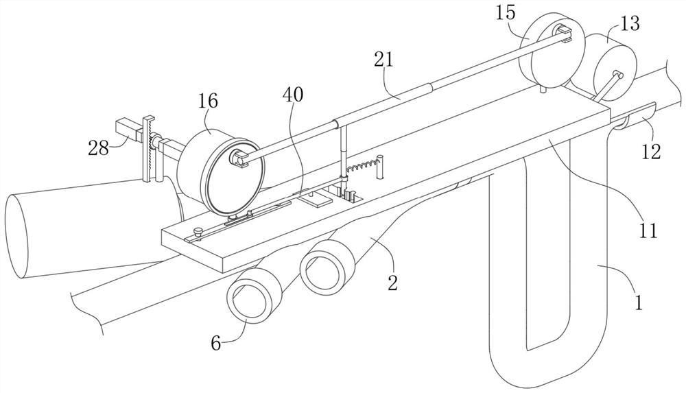
[0031] see Figure 1-Figure 2 , a device for controllable steering of pressure conduction at the head end of a medical nasogastric feeding catheter in the illustration includes a connecting assembly 2 communicated with the catheter 1; a push assembly 10 is used to push and fit the catheter 1 when the connecting assembly 2 operates. The pushing assembly 10 is arranged on the catheter 1 .
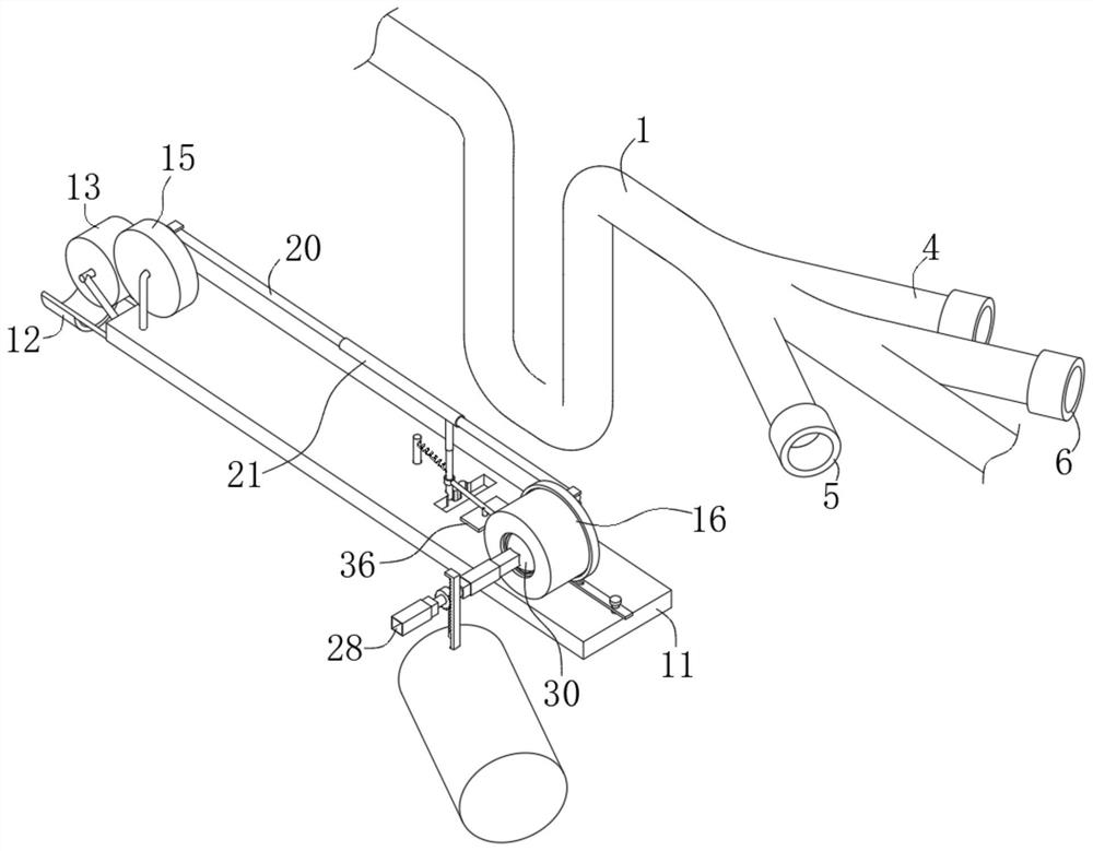
[0032] see Figure 2-Figure 3 , the connecting assembly 2 in the figure includes an expansion connecting pipe 4 and a curved connecting pipe 5 and an injection connecting pipe 6 which are distributed obliquely and communicated with the catheter 1. A controller, the curved connecting pipe 5 is used to connect to the third controller that controls the front end of the curved catheter 1, and the injection connecting pipe 6 is used to connect to the second controller that controls the injection of contrast medium.
[0033] see Figure 4 , the push assembly 10 in the figure includes a fixed pla...
Embodiment 2
[0044] see Figure 8-Figure 10 , the adjustment assembly 30 in the figure includes a fixed ball 31, a through groove 32 is formed on the fixed ball 31, a first movable groove 33 is opened on the side of the second rotating plate 16, and the first movable groove 33 is fixedly connected to the through groove 32. The matching limit post 34 is fixedly connected to the inner wall of the first movable groove 33 with a limit ring 35 which is press-fitted with the fixed ball 31 .
[0045] In this embodiment, after the angle of the third set of rods 29 changes, it drives the fixed ball 31 to rotate, the limit post 34 moves in the through groove 32 and automatically adjusts the position, the fixed ball 31 is always located in the first movable groove 33, and passes through the limit post 34 , the second rotating plate 16 is rotated along the collar 17 .
Embodiment 3
[0047] see Figure 5-Figure 7 , the flip assembly 36 in the figure includes a rotating plate 37 that is fixedly connected with the rotating rod 18, the two ends of the rotating plate 37 and the fixed plate 11 are provided with mutually adapted insertion holes 38, and the middle of the rotating plate 37 is provided with a sliding slot 39, A movable rod 40 is slidably connected in the sliding groove 39, and an end of the movable rod 40 is rotatably connected with a telescopic rod 41 that is connected and fixed with the first sleeve 21. The fixing plate 11 is provided with a second movable slot 43 , and the fixing plate 11 is also provided with two clamping slots 44 communicating with the second movable slot 43 . A rotating rod 7 is rotatably connected between the two grooves, and a tension spring 8 is hooked between the telescopic rod 41 and the rotating rod 7 .
[0048] In this embodiment, when the third controller is running, the third set of rods 29 is located on the side of...
PUM
 Abstract
Description
Claims
Application Information
 - R&D
- Intellectual Property
- Life Sciences
- Materials
- Tech Scout
- Unparalleled Data Quality
- Higher Quality Content
- 60% Fewer Hallucinations
Browse by: Latest US Patents, China's latest patents, Technical Efficacy Thesaurus, Application Domain, Technology Topic, Popular Technical Reports.
© 2025 PatSnap. All rights reserved.Legal|Privacy policy|Modern Slavery Act Transparency Statement|Sitemap|About US| Contact US: help@patsnap.com


