Medical clinical drainage device
A clinical and medical technology, applied in the direction of suction devices, catheters, etc., can solve the problems of hindering the normal circulation of blood in the limbs, the tape is easy to fall off, etc., and achieve the effect of convenient use and unique structure
- Summary
- Abstract
- Description
- Claims
- Application Information
AI Technical Summary
Problems solved by technology
Method used
Image

Examples
Embodiment 1
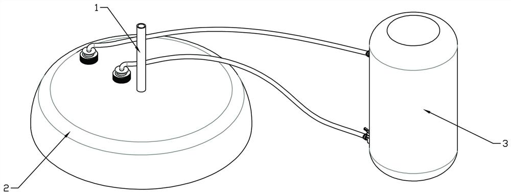
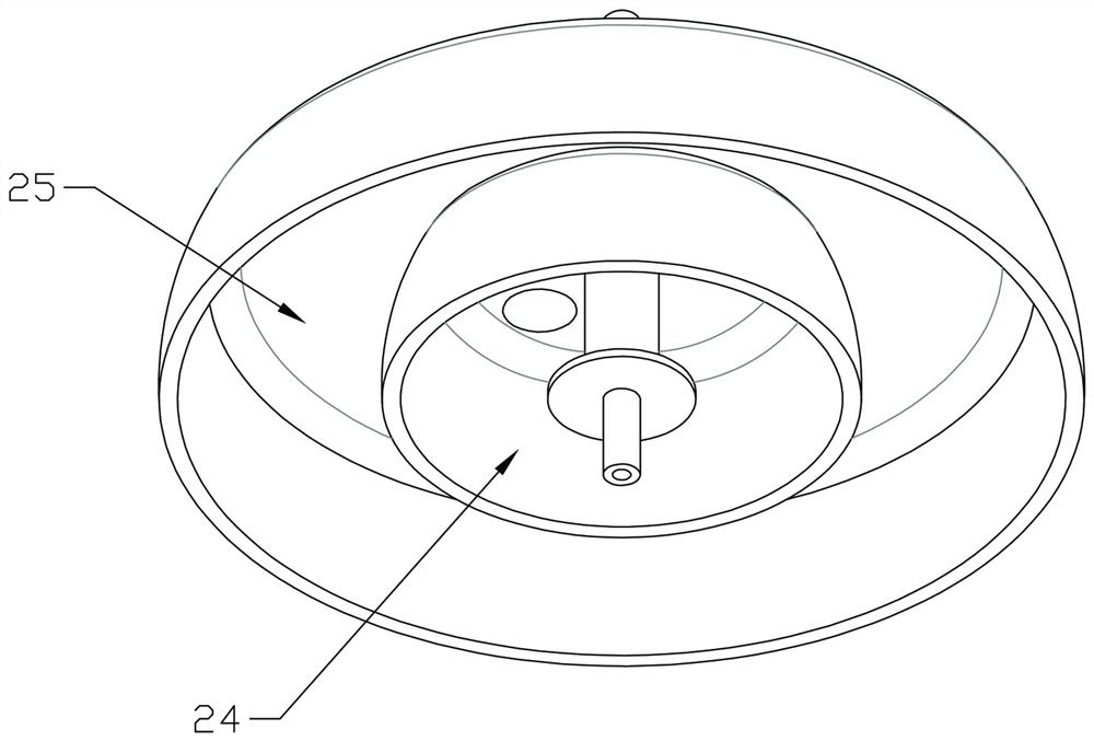
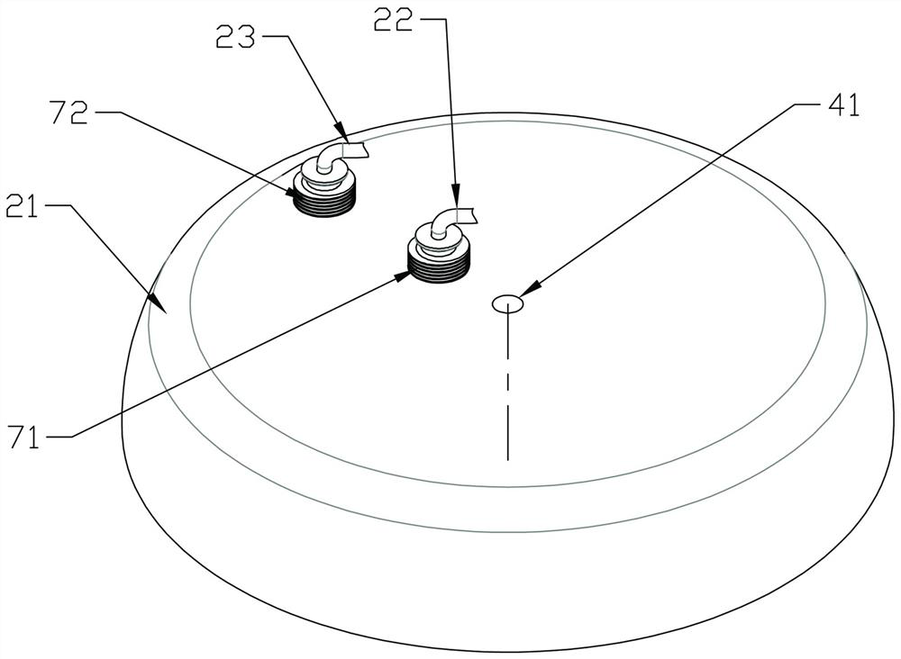
[0040] This embodiment provides a drainage device for clinical use, such as Figure 1-6 As shown, it includes an adsorption and drainage unit 2, an adsorption control unit 3 and a drainage pipe 1. The adsorption and drainage unit 2 includes an anti-seepage cover 21, a positive pressure pipe 22 and a negative pressure pipe 23. The middle of the anti-seepage cover 21 is provided with a bottom The open positive pressure cavity 24, the anti-seepage cover member outside the positive pressure cavity 24 is provided with an annular negative pressure cavity 25 with an open bottom, and the negative pressure cavity 25 and the positive pressure cavity 24 are arranged coaxially, specifically :
[0041] like figure 2 and Figure 5 As shown, the anti-seepage cover member 21 includes a top cover 211, an outer spacer ring 212 and an inner spacer ring 213. The outer shelf ring 212 is coaxially fixed on the bottom surface of the top cover 211. The annular surface is flush, and the connection...
Embodiment 2
[0055] The control bottle of the adsorption control unit in the medical clinical drainage device provided in Example 1 is a disposable component and cannot be reused.
[0056] In view of the above problems, the medical clinical drainage device provided in this embodiment is different from Embodiment 1 in that: Figure 12-13 As shown, the medical clinical drainage device provided in this embodiment further includes a charging mechanism, and the charging mechanism includes a one-way intake valve and a stamping assembly, and the one-way intake valve 36 is matched and installed on the control bottle, and the one-way intake valve 36 is installed on the control bottle. The exhaust end of the intake valve is communicated with the lower control chamber, the air inlet of the one-way intake valve is movably connected with the charging component, and the charging component can inject high-pressure gas at a constant pressure into the downward control chamber through the one-way intake valv...
Embodiment 3
[0059] The difference between Example 3 and Example 2 is that, as Figure 14 As shown, the length dimension of the guide column is a, the thickness dimension of the annular pressure plate is b, and the height dimension of the inner spacer ring is c, where a+b=c, so that the impermeable cover 21 is adsorbed on the patient When it is on the skin, the guide column will press down the annular pressure plate and touch the patient's skin, so that the negative pressure in the negative pressure chamber is used to assist the high pressure in the positive pressure chamber to press the annular pressure plate and the patient's skin together, further. The fixing strength of the drainage tube is improved.
[0060] Example 3
[0061] The difference between Example 3 and Example 2 is that the anti-seepage cover is matched with a pressure relief hole that communicates with the negative pressure chamber, and is fitted with a pressure relief valve. After the patient drainage treatment is complete...
PUM
 Abstract
Description
Claims
Application Information
PatSnap Eureka turns technology decisions into work you can execute. Powered by our Innovation Knowledge Graph, it runs expert workflows across engineering, life sciences, materials and intellectual property. Get your review-ready output in minutes.


