Mine ore material magnetic separation and distribution equipment

A magnetic separation and mining technology, applied in the field of magnetic separation and material separation equipment, can solve the problems of iron powder screening and removal, affecting the production quality of ore materials, etc.

Pending Publication Date: 2022-07-29
CHINA NAT INST OF STANDARDIZATION
View PDF0 Cites 1 Cited by
  • Summary
  • Abstract
  • Description
  • Claims
  • Application Information

AI Technical Summary

Problems solved by technology

Although the above patent can evenly separate the materials, it fails to screen and remove the

Method used


Image

  • Mine ore material magnetic separation and distribution equipment
  • Mine ore material magnetic separation and distribution equipment
  • Mine ore material magnetic separation and distribution equipment

Examples


Embodiment 1

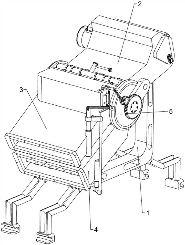
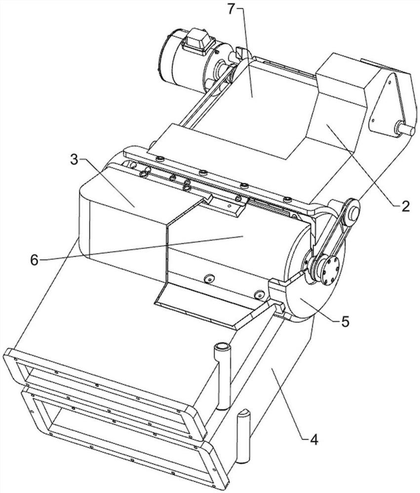
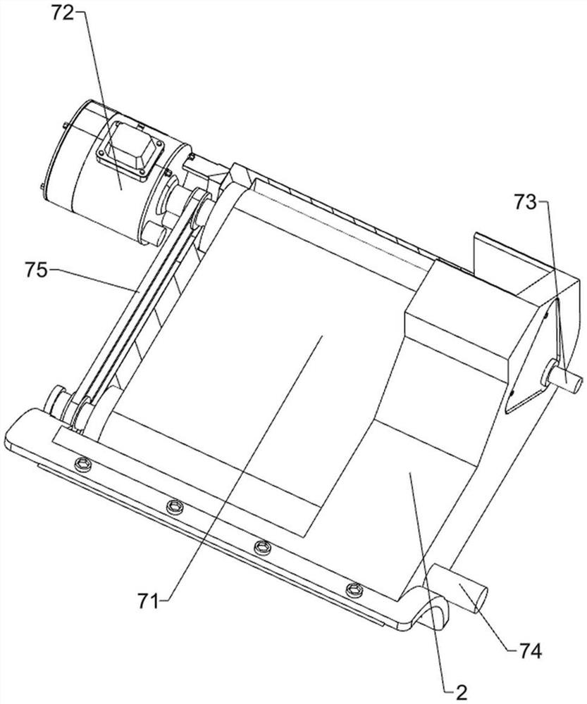
[0040] A magnetic separation and distribution equipment for mine minerals, such as Figure 1-Figure 5 As shown, it includes a supporting chassis 1, a feeding square pipe 2, a first discharging pipe 3, a second discharging pipe 4, a screening cylinder 5, a screening roller 6, a feeding mechanism 7 and a material distribution mechanism 8 , the upper right part of the support chassis 1 is connected with a feeding square tube 2, the left part of the feeding square tube 2 is connected with a sieve cylinder 5 by means of bolt connection, and the upper side of the left part of the sieve cylinder 5 is connected with a first The discharge pipe 3, the lower left side of the screen cylinder 5 is connected with a second discharge pipe 4, the feeding square pipe 2 is connected with a feeding mechanism 7, and the feeding mechanism 7 can realize the discharge of mineral materials, feeding A material distribution mechanism 8 is connected between the mechanism 7 and the screening cylinder 5. T...

Embodiment 2

[0045] On the basis of Example 1, as Figure 6-Figure 10 As shown, it also includes a cleaning mechanism 9. The cleaning mechanism 9 includes a drive toothed disc 91, a first driven gear 92, a rotating circular seat 93, a first hinge rod 94, a traverse crossbar 95, and a second hinge rod. 96. The cleaning brush 97, the fixed horizontal frame 98 and the fixed short rod 99, the front part of the fixed short shaft 81 is fixedly connected with a drive toothed plate 91, and the upper left side of the front part of the screen cylinder 5 is connected with a rotating round seat 93 in a rotary manner, and the rotating The front part of the round seat 93 is fixed with a first driven gear 92, the first driven gear 92 is meshed with the driving gear plate 91, the middle part of the rotating round seat 93 is rotatably connected with a first hinge rod 94, and the upper part of the first discharge pipe 3 The right front side is slidably connected with a traverse bar 95, the front part of the...

Embodiment 3

[0052] On the basis of Example 1 and Example 2, as Figure 13 and Figure 18 As shown, it also includes a blowing mechanism 12, the blowing mechanism 12 includes a blowing round pipe 121 and an air inlet pipe 122, and a blowing round pipe 121 is embedded in the middle of the upper part of the screen cylinder 5, and the blowing round pipe 121 can be The material is blown off, and the air inlet pipe 122 is connected to the middle of the air blowing round pipe 121 .

[0053] A cover 123 is also included, and a cover 123 is threadedly placed at the front of the air intake pipe 122 .

[0054] First, the operator opens the cover 123 to connect the air inlet pipe 122 to an external fan. When people use the device, the air blowing pipe 121 blows air to the screen cylinder 5, and then blows the unadsorbed substances into the second discharge pipe 4. , when the device is not needed, stop externally connecting the air inlet pipe 122, and then cover the cover 123, so that the mineral scre...


PUM


Abstract

The invention relates to material separation equipment, in particular to magnetic separation material separation equipment for mine ore materials. According to the magnetic separation and distribution equipment for the mine ore materials, iron powder in the ore materials can be screened and removed, and the production quality of the ore materials is not affected. Magnetic separation equipment for mine ore materials comprises a supporting bottom frame, a feeding square pipe and a first discharging pipe, the feeding square pipe is connected to the upper side of the right portion of the supporting bottom frame, a screening cylinder is connected to the left portion of the feeding square pipe in a bolt connection mode, and the first discharging pipe is connected to the upper side of the left portion of the screening cylinder. A proper amount of ore materials are poured in, the servo motor is started, then iron powder is adsorbed to the screening cylinder through the magnetic separation frame, the ore materials which are not adsorbed fall into the second discharging pipe through the screening cylinder to be discharged, meanwhile, when the iron powder rotates reversely to the left side, the iron powder also falls into the first discharging pipe to be discharged, and therefore the iron powder is discharged through the first discharging pipe. And iron powder in ore materials can be screened and removed, and the production quality of the ore materials is not affected.

Description

technical field [0001] The invention relates to a material distributing equipment, in particular to a magnetic separation material distributing equipment for mine minerals. Background technique [0002] With the advancement of science and technology and the improvement of the level of mining production, most people will screen and divide ore materials to facilitate subsequent processing. [0003] Patent application CN215047104U provides a silo uniform feeding and distributing device, including a box body, the left side of the box body is connected with two mutually meshing first gears and second gears, the first gear of the first gear The center hole is connected with a first rotating shaft, the side of the first rotating shaft extending into the box is connected with a first paddle, the second center hole of the second gear is connected with a second rotating shaft, the One side of the second rotating shaft extending into the box body is connected with a second paddle, and...

Claims


Application Information

Patent Timeline
IPC IPC(8): B03C1/30
CPCB03C1/30
Inventor 韩冰付强张欣亮王春艳
Owner CHINA NAT INST OF STANDARDIZATION
Why Eureka
Try Eureka