
Furnace body cutting device of biomass gasifier

A technology of cutting device and gasifier, which is applied in the direction of combination device, chemical instrument and method, separation method, etc., can solve the problems of easy leakage of high-temperature cutting steam and poor fixing effect of workpiece, and achieves increased contact time and increased The effect of cooling rate

Pending Publication Date: 2022-07-29
张家港市天源机械制造有限公司
View PDF0 Cites 0 Cited by
  • Summary
  • Abstract
  • Description
  • Claims
  • Application Information

AI Technical Summary

Problems solved by technology

[0004] Aiming at the deficiencies of the prior art, the present invention provides a furnace body cutting device for a biomass gasification furnace, which solves the problem that the high-temperature cutting steam of the traditional laser cutting equipment is easy to leak out and the fixing effect of the workpiece is poor

Method used


Image

  • Furnace body cutting device of biomass gasifier
  • Furnace body cutting device of biomass gasifier
  • Furnace body cutting device of biomass gasifier

Examples


Embodiment 1

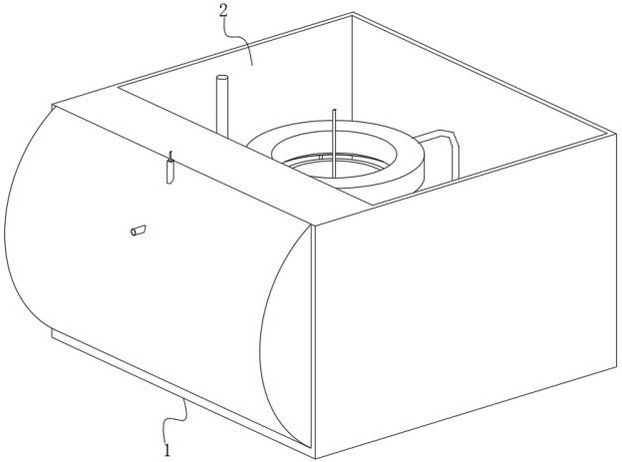
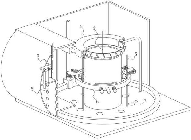
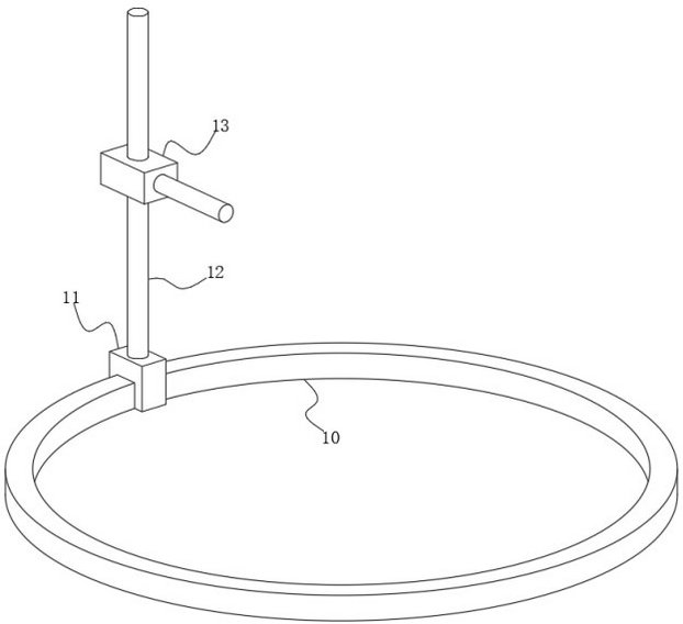
[0036] see Figure 1-10 , the present invention provides a technical solution: a furnace body cutting device for a biomass gasification furnace, comprising a bottom plate 1, an outer cover 2 is fixedly connected to the upper surface of the bottom plate 1, and a rotating machine 3 is arranged inside the outer cover 2, and the rotating machine 3 An air cooler 4 is arranged on the outside of the air cooler 4, a fixing rod 5 is fixedly connected to the lower surface of the air cooler 4, and a fixing machine 6 is slidably connected to the outer surface of the fixing rod 5. The port 7 is opened in the wall of the bottom plate 1, the wall on the left side of the outer cover 2 is provided with a through hole 8, the outside of the through hole 8 is provided with a suction machine 9, the upper surface of the bottom plate 1 is fixedly connected with an annular guide rail 10, the annular guide rail 10 A slider 11 is slidably connected to the outer surface of the slider 11 , a guide rod 12...

Embodiment 2

[0043] see Figure 1-10 , the present invention provides a technical solution: on the basis of the first embodiment, the suction machine 9 includes a side cover 30, the upper surface of the side cover 30 is fixedly connected with a fixing plate 31, and the lower surface of the side cover 30 is rotatably connected with a rotating plate 32. The top of the turning plate 32 is provided with a T-shaped plate 33, the inner surface of the T-shaped plate 33 is fixedly connected with a water inlet pipe 34, and the right end of the water inlet pipe 34 is provided with a purification pipeline 35. The inner surface of the pipe 40 is movably connected with a regulating valve 41, the right side of the regulating valve 41 is provided with a connecting pipe 42, the wall of the connecting pipe 42 is provided with a connecting hole 43, and the inner surface of the connecting pipe 42 is slidably connected with a stopper 45, which stops the A vertical rod 44 is fixedly connected to the inner surf...


PUM


Abstract

The invention discloses a furnace body cutting device of a biomass gasifier, and relates to the technical field of cutting. The furnace body cutting device comprises a bottom plate, an outer cover is fixedly connected to the upper surface of the bottom plate, a rotating machine is arranged in the outer cover, and an air cooling machine is arranged outside the rotating machine. According to the furnace body cutting device of the biomass gasification furnace, by arranging the adjusting valve, when equipment is used, along with separation of the bottommost check block and the right end of the control rod, the elastic piece extends, the cover plate on the left side of the fixed block makes contact with and is attached to the outer surface of the fixed block, and air inflow of the bent pipe is stopped; and at the moment that the adjusting valve is opened, gas rushes into the pipeline, the adjusting valve plays a role in stopping and controlling the flow, and the problem that cutting waste cannot be treated in traditional cutting equipment is solved.

Description

technical field [0001] The invention relates to the technical field of cutting, in particular to a furnace body cutting device of a biomass gasification furnace. Background technique [0002] Laser cutting uses a high-energy-density laser beam to heat the workpiece, so that the temperature rises rapidly, reaching the boiling point of the material in a very short time, and the material begins to vaporize to form vapor. These vapors are ejected at a high velocity, and at the same time as the vapors are ejected, cuts are formed in the material. With the continuous development of the storage tank industry, more and more industries and enterprises use laser cutting. [0003] When the traditional laser cutting device cuts the tank body, due to the lack of fixed protective equipment inside and outside the tank body, the vibration of the equipment operation will cause the tank body to shake, affecting the cutting accuracy, and high temperature laser cutting will leave a large amoun...

Claims


Application Information

Patent Timeline
Patent Type & Authority Applications(China)
IPC IPC(8): B23K26/16B23K26/38B23K26/70B01D50/00B01D50/10
CPCB23K26/38B23K26/16B23K26/702B01D50/00
Inventor 赵一君
Owner 张家港市天源机械制造有限公司
Learn More