Hammer processing device capable of cleaning and recycling chippings
A technology of processing devices and hammers, which is applied in metal processing, shearing devices, metal processing equipment, etc., can solve problems such as splashing, hurting workers, and worker injuries
- Summary
- Abstract
- Description
- Claims
- Application Information
AI Technical Summary
Problems solved by technology
Method used
Image
Examples
Embodiment 1
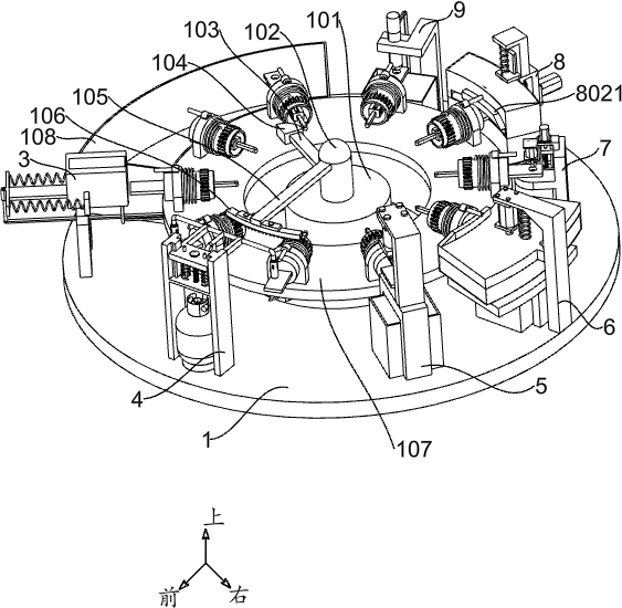
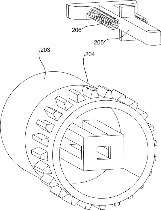
[0034] A hammer processing unit that cleans and recycles debris, such as Figure 1-Figure 13 As shown, it includes a bottom plate 1, a first fixed column 101, a second fixed column 102, an indexing plate 107, a punching machine 5, a first waste collection frame 501, a steel plate loading mechanism, an automatic feeding mechanism and a steel plate heating mechanism, The side of all parts facing the center of the circle is the inner side, and the side away from the center of the circle is the outer side. If there are two symmetrical parts, the surface between the two parts is the inner side. A first fixing column 101 is fixed in the middle of the top wall of the bottom plate 1. A second fixing column 102 is fixed in the middle of the top wall of a fixed column 101, and an indexing plate 107 is installed on the top of the bottom plate 1. The indexing plate 107 will stop for a period of time every 36 degrees of rotation. A punching machine 5, the punching machine 5 is the prior ar...
Embodiment 2
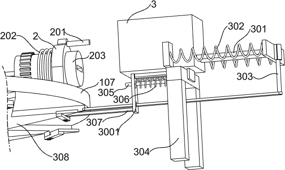
[0037] On the basis of Example 1, as Figure 3-Figure 5 As shown, the automatic feeding mechanism includes a storage frame 3, a second fixed plate 3001, a sliding push plate 301, a second spring 302, an L-shaped sliding rod 303, a first support frame 304, a first guide rod 305, a first Three springs 306, a third connecting rod 307, a feeding gear ring 308, a fourth connecting rod 309, and a triangular inclined block 310, a first support frame 304 is fixed at the front left of the top wall of the bottom plate 1, and a top of the first support frame 304 is provided with A slideway, a storage frame 3 is slidably connected to the top of the first support frame 304, a slider is arranged at the bottom of the storage frame 3, and a second fixing plate 3001 is installed on the inner side of the bottom of the storage frame 3. The plate 3001 is located on the inner side wall of the bottom slider of the storage frame 3. A third connecting rod 307 is fixed at the bottom of the inner wall ...
Embodiment 3
[0046] On the basis of Example 2, as Figure 8-Figure 9 As shown, it also includes a third support frame 6, a No. 1 motor 601, a fifth spring 602, a first sliding cover 603, a cutting plate 604, a first collection funnel 605, a first fixed frame 606 and a second waste collection frame 607, a third support frame 6 is fixed on the right rearward position of the bottom plate 1, a slide rail is arranged on the inner wall of the third support frame 6, and a No. 1 motor 601 is installed on the top of the third support frame 6, and the No. 1 motor 601 is facing downward, a first sliding cover 603 is slidably connected to the inner wall of the third support frame 6, and a fixing plate is arranged on the inner side of the top wall of the first sliding cover 603. The first sliding cover 603 and the third support frame A fifth spring 602 is connected between 6. The output shaft of the No. 1 motor 601 passes through the first sliding cover 603 and is connected with a cutting plate 604. Th...
PUM
 Abstract
Description
Claims
Application Information
 - R&D
- Intellectual Property
- Life Sciences
- Materials
- Tech Scout
- Unparalleled Data Quality
- Higher Quality Content
- 60% Fewer Hallucinations
Browse by: Latest US Patents, China's latest patents, Technical Efficacy Thesaurus, Application Domain, Technology Topic, Popular Technical Reports.
© 2025 PatSnap. All rights reserved.Legal|Privacy policy|Modern Slavery Act Transparency Statement|Sitemap|About US| Contact US: help@patsnap.com


