Machine tool for producing shaft parts

A technology for shaft parts and processing machine tools, applied in the field of shaft parts production equipment, can solve problems such as shaft processing deformation and affecting processing accuracy

Inactive Publication Date: 2022-07-29
葛恒伟
View PDF1 Cites 3 Cited by
  • Summary
  • Abstract
  • Description
  • Claims
  • Application Information

AI Technical Summary

Problems solved by technology

[0005] The invention provides a processing machine tool for the production of shaft parts, aiming at clamping and fixing the shaft only from both ends of the shaft, most of the shaft is in a suspended state, and under the influence of other factors such as gravity or centrifugal force, the shaft cannot Deformation may occur during processing, which affects the accuracy of processing

Method used


Image

  • Machine tool for producing shaft parts
  • Machine tool for producing shaft parts
  • Machine tool for producing shaft parts

Examples


Embodiment 1

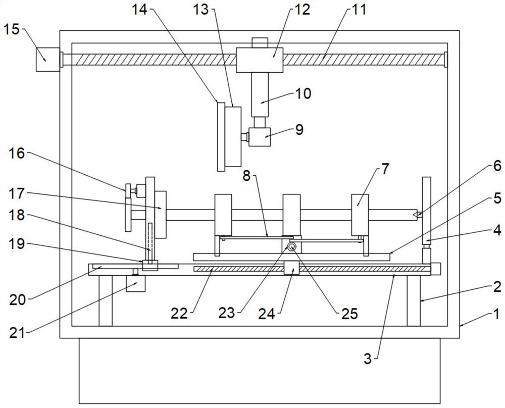
[0059] Embodiments of the present invention provide a processing machine tool for the production of shaft parts, such as figure 1 As shown, it includes a frame 1, a workbench 3 and a fixture unit, and the workbench 3 is installed on the frame 1. In this embodiment, preferably, the workbench 3 is connected to the frame 1 through a plurality of spaced support rods 2. Fixed connection, the two ends of the support rod 2 can be respectively fixed with the frame 1 and the workbench 3 by welding, and the clamp unit is installed on the workbench 3 for clamping both ends of the shaft. Specifically, the clamp unit includes:

[0060] The chuck assembly on the table 3 is used to fix one end of the shaft;

[0061] The top assembly on the table 3 is used to fix the other end of the shaft;

[0062] The processing machine tool for the production of shaft parts also includes a support unit installed on the worktable 3, and the support unit includes:

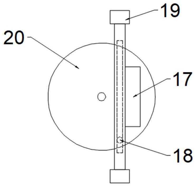
[0063] A mounting plate 5 arranged above...

Embodiment 2

[0090] In specific implementation, as figure 1 and Figure 8 As shown, the processing machine tool for the production of shaft parts also includes a processing unit installed on the frame 1 and located above the worktable 3, and the processing unit includes:

[0091] For the second motor 9, a mounting shell 13 is fixed on the output shaft of the second motor 9, and a grinding disc 14 is fixedly mounted on the side wall of the mounting shell 13 away from the second motor 9. The size of the grinding disc 14 shown is larger than The size of the mounting shell 13, the grinding disc 14 can be fixedly connected with the mounting shell 13 by screws, and the mounting shell 13 is driven by the second motor 9 to drive the grinding disc 14 to rotate, so that the shaft surface can be ground;

[0092]A plurality of second electric push rods 35 are fixedly installed in the mounting shell 13 at circumferential intervals, and the telescopic end of each second electric push rod 35 is installe...

Embodiment 3

[0095] The difference between this embodiment and Embodiment 2 is that a chip cleaning unit 36 ​​is further included, and the chip cleaning unit 36 ​​includes:

[0096] A support rod 2 hinged at one end of the workbench 3, the support rod 2 is fixed on the frame 1;

[0097] The third connecting rod 38 is hinged at the other end of the table 3, the third connecting rod 38 is eccentrically hinged with the disk 39, the disk 39 is fixed on the output shaft of the sixth motor, and the sixth motor is fixed on the frame 1, The six motors drive the disc 39 to rotate, the disc 39 drives the third link 38 to move, and the third link 38 drives the worktable 3 to reciprocate and tilt to swing, which helps the debris on the worktable 3 to fall from the worktable 3 and avoids breaking. Chip accumulation affects the machining quality and the life of machine components;

[0098] a plurality of second hemispheres protruding on the end face of the disc 39 close to the third connecting rod 38 a...


PUM


Abstract

The invention is applicable to the technical field of shaft part production equipment, and provides a machining tool for shaft part production, which comprises a rack, a workbench and a clamp unit, and further comprises a supporting unit mounted on the workbench, the supporting unit comprises a mounting plate, a plurality of supporting pieces, an adjusting assembly and a moving assembly, the clamp unit comprises a chuck assembly and a tip assembly, and each supporting piece comprises an inner sleeve, an outer sleeve, a mounting rod, a supporting roller, a spherical protrusion, a first spring, a first hemispherical protrusion, a ratchet ring, a pawl and a second spring. Multi-point supporting can be fully carried out on the shaft, the situation that the machining precision is affected due to deformation of the shaft is reduced, and the distance between the adjacent supporting pieces is adjusted through the adjusting assemblies to adapt to shafts of different lengths; the clamp unit is arranged, so that shafts with different lengths can be clamped and fixed; and the supporting piece can support shafts with different diameters.

Description

technical field [0001] The invention belongs to the technical field of shaft parts production equipment, and particularly relates to a processing machine tool for shaft parts production. Background technique [0002] In industrial products, shaft parts are suitable for the maintenance of one or more CNC machine tool parts, and are commonly used parts in the processing and production of mechanical equipment. They are mainly used to support transmission parts, transmit torque and bear loads; [0003] Shaft parts are processed by machine tools. Chinese patent CN113084212A discloses a CNC machining machine tool for processing long shaft parts, including a machine table, a three-jaw chuck and a positioning and clamping mechanism. The positioning and clamping mechanism includes a base, a positioning Main cylinder, positioning ejector rod, fixed disc, clamping auxiliary cylinder and clamping components. The positioning mandrel is fixedly connected with the main piston rod, the fix...

Claims


Application Information

Patent Timeline
Patent Type & Authority Applications(China)
IPC IPC(8): B24B5/04B24B9/02B24B41/00B24B41/02B24B41/06B24B47/12B24B47/16B24B55/06
CPCB24B5/04B24B9/02B24B47/12B24B47/16B24B41/062B24B41/067B24B41/02B24B41/00B24B55/06
Inventor 葛恒伟
Owner 葛恒伟
Why Eureka
Try Eureka