Plastic well injection molding device with wall thickness adjusting function

A technology of injection molding and plastic wells, applied in the field of plastic well injection molding, can solve the problems of slow discharge speed of plastic wells, inability to adjust wall thickness, detection impact, etc., to improve the overall intelligence level, promote uniform heating effect, and reduce energy consumption The effect of loss

Inactive Publication Date: 2022-07-29
上海泓伟新材料有限公司
View PDF0 Cites 2 Cited by
  • Summary
  • Abstract
  • Description
  • Claims
  • Application Information

AI Technical Summary

Problems solved by technology

[0003] Due to its special shape, the plastic well needs to be integrally formed. Conventional injection molding devices are difficult to demould after molding, and it is also difficult to remove the mold inside the plastic well, which leads to a slow discharge speed of the plastic well.
The traditional discharge is done manually, which is inefficient, and the placement of the discharge is also lack of stability, which has a certain degree of influence on the subsequent detection
[0004] On the other hand, the traditional injection plastic is mostly output through the screw output machine during transportation, and the screw output machine is prone to heat accumulation on the surface when heating the injection plastic, which affects the speed of heat transfer and the uniform distribution of heat. There is a temperature difference between the injection molding areas, and it is prone to local unqualified strength during molding
[0005] The traditional plastic well injection molding device cannot adjust the wall thickness, and can only produce plastic wells of one size, and there is a sequence of cooling areas during cooling, which is prone to stress concentration

Method used


Image

  • Plastic well injection molding device with wall thickness adjusting function
  • Plastic well injection molding device with wall thickness adjusting function
  • Plastic well injection molding device with wall thickness adjusting function

Examples


Embodiment Construction

[0028] The technical solutions in the embodiments of the present invention will be clearly and completely described below with reference to the accompanying drawings in the embodiments of the present invention. Obviously, the described embodiments are only a part of the embodiments of the present invention, rather than all the embodiments. Based on the embodiments of the present invention, all other embodiments obtained by those of ordinary skill in the art without creative efforts shall fall within the protection scope of the present invention.

[0029] see Figure 1-Figure 9 , the present invention provides technical scheme:

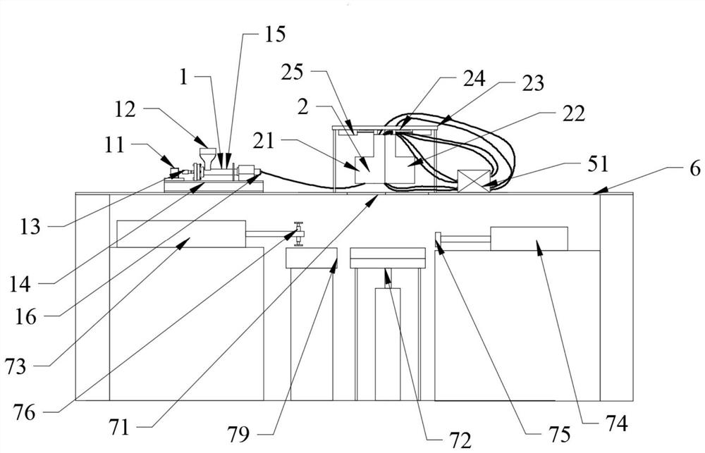
[0030] like Figure 1-Figure 9 As shown, a plastic well injection molding device with wall thickness adjustment function includes a feeding component 1, an outer mold 2, an inner mold 3, a thickness adjustment component 4, a cooling component 5, a lower frame 6, and a discharging component 7. The feeding assembly 1, the outer mold 2 and the lower fra...


PUM


Abstract

The invention discloses a plastic well injection molding device with a wall thickness adjusting function, and relates to the technical field of plastic well injection molding, the plastic well injection molding device comprises a feeding assembly, an outer mold, an inner mold, a thickness adjusting assembly, a cooling assembly, a lower rack and a discharging assembly, the feeding assembly, the outer mold and the lower rack are in fastening connection, and the inner mold and the outer mold are in fastening connection; one end of the thickness adjusting assembly is arranged on the inner surface of the outer mold, the other end of the thickness adjusting assembly is arranged on the outer surface of the inner mold, one end of the cooling assembly is fixedly connected with the lower rack, and the other end of the cooling assembly is embedded into the outer mold and the inner mold. According to the feeding assembly, temperature difference energy is converted into continuous vibration energy, the uniform heating effect of injection molding materials is promoted, the heating speed is increased, and energy loss is reduced. The wall thickness of the plastic well can be intelligently adjusted through the thickness adjusting assembly, and products of various specifications can be produced through one forming device.

Description

technical field [0001] The invention relates to the technical field of plastic well injection molding, in particular to a plastic well injection molding device with a wall thickness adjustment function. Background technique [0002] Plastic wells mainly refer to plastic inspection wells, which are usually set at the intersection of plastic drainage pipes, where the diameter and slope of the pipes change, and at the turning points, which are convenient for regular inspection, cleaning and dredging of drainage auxiliary buildings. Most of the plastic wells are one-time injection molding, but the traditional plastic well injection equipment has certain defects. [0003] Due to its special shape, the plastic well needs to be integrally formed. The conventional injection molding device is difficult to demould after molding, and the mold inside the plastic well is also difficult to take out, resulting in a slow discharge rate of the plastic well. The traditional discharge is done...

Claims


Application Information

Patent Timeline
Patent Type & Authority Applications(China)
IPC IPC(8): B29C45/17B29C45/40B29C45/47B29C45/73B29C45/76
CPCB29C45/1751B29C45/47B29C45/73B29C45/7686B29C45/40B29C45/1769
Inventor 杨琳林
Owner 上海泓伟新材料有限公司
Why Eureka
Try Eureka