Ceramic heater and method for making the same

a ceramic heater and ceramic technology, applied in the direction of heater elements, heater heating arrangements, resistive material coatings, etc., can solve the problems of widening the temperature difference between the center and the periphery, deteriorating the uniform heating property, etc., to prevent the flow of current in the wafer, good uniform heating property, and resistivity does not decrease

Active Publication Date: 2011-03-17
NGK INSULATORS LTD
View PDF1 Cites 10 Cited by
  • Summary
  • Abstract
  • Description
  • Claims
  • Application Information

AI Technical Summary

Benefits of technology

[0014]The inventors of the present invention have investigated the cause of deterioration of the uniform heating property at high temperatures higher than the designed temperature and conceived that the cause may be an increased contribution to heat release made by radiation heat transfer among three types of heat conduction at high temperatures. In other words, according to conventional ceramic heaters, since a shaft is bonded to the central portion, the amount of heat escaping from the central portion of the ceramic plate is large at low temperatures due to a large contribution made by solid heat conduction dominant at low temperatures, and thus the temperature of central portion is prevented from increasing. However, at high temperatures, because the contribution by the radiant heat conduction is relatively large and heat easily escapes by radiation from the peripheral portion having no shaft compared to the central portion of the ceramic plate, the amount of heat released by radiation from the peripheral portion becomes relatively high and the temperature of the peripheral portion becomes lower than that of the central portion, thereby deteriorating the uniform heating property at high temperatures. According to the ceramic heater of the invention of the subject application, the molybdenum carbide content in the resistive heating element is higher in the middle portion than in the peripheral portion. Since the temperature coefficient of resistance of molybdenum carbides is lower than that of molybdenum, the resistance value does not increase in the middle portion as much as it does in the peripheral portion even when the temperature is increased. In a unicursal-shape resistive heating element, the magnitude of the current is the same irrespective of the position, and thus the amount of heat generated in the middle portion of the resistive heating element does not increase as much as that in the peripheral portion despite the increase in temperatures. In contrast, the resistance value of the peripheral portion of the resistive heating element increases relatively largely and thus the amount of heat generated in the peripheral portion increases relatively significantly. Accordingly, the relative increase in radiant heat release from the peripheral portion at high temperatures is compensated thereby, and the increase in the difference in temperature between the peripheral portion and the middle portion can be suppressed. As a result, compared to a ceramic heater in which the molybdenum carbide content in the resistive heating element is homogeneous in all parts, the uniform heating property does not easily deteriorate despite the increase in temperature. In other words, a good uniform heating property can be obtained in a wide range of operation temperatures.
[0015]According to the ceramic heater of the present invention, the middle portion of the resistive heating element may be a portion included in the circular shaft-opposing region opposing the cylindrical shaft. In this case, the molybdenum carbide content of the resistive heating element may be higher in a region included in a shaft-opposing region than in the peripheral portion. In this manner, the increase in difference in temperature between the peripheral portion and the shaft-opposing region can be suppressed. Accordingly, the deterioration of the uniform heating property caused by the shaft can be further suppressed.
[0017]According to the ceramic heater of the present invention, a carbon content of the ceramic plate may be higher in a portion in which the middle portion of the resistive heating element is buried than in a portion in which the peripheral portion of the resistive heating element is buried, and the portion in which the middle portion of the resistive heating element in the ceramic plate is buried may be unexposed on a surface of the ceramic plate which is opposite to the surface of the ceramic plate jointed to the cylindrical shaft. In this manner, even if there is a portion in which a carbon content of the ceramic plate is higher than in the other portion, the resistivity does not decrease in the surface of the ceramic plate which is opposite to the surface of the ceramic plate jointed to the cylindrical shaft. As a result, leakage current flowing in a wafer can be prevented when the ceramic plate heats the wafer.
[0022]According to the ceramic heater made by this method for making the ceramic heater, the molybdenum carbide content in the resistive heating element is higher in the middle portion than in the peripheral portion. As a result, according to this method for making the ceramic heater, as with the ceramic heater of the present invention described above, a ceramic heater having a good uniform heating property in a wide range of operation temperatures can be obtained.
[0023]According to the first method for manufacturing a ceramic heater of the present invention, in step (a), the aluminum nitride raw material having a higher carbon content may be placed in the die so as to be unexposed on a surface of the ceramic plate which is opposite to the surface of the ceramic plate jointed to the cylindrical shaft in step (c). In this manner, even if the aluminum nitride raw material having a high carbon content is placed in the die in step (a), the resistivity does not decrease in the surface of a ceramic plate, obtained by step (b), which is opposite to the surface of the ceramic plate jointed to the cylindrical shaft. As a result, leakage current flowing in a wafer can be prevented when the ceramic plate heats the wafer.

Problems solved by technology

For example, when the resistive heating element is heated so that the ceramic heater has a temperature higher than the designed temperature, a hot spot is generated near the center of the heating surface of the ceramic plate, thereby widening the temperature difference between the center and the periphery and deteriorating the uniform heating property.
However, in recent years, there has arisen a need to change temperature during a process and a heater having a uniform heating property that does not easily degrade despite the temperature changes is desired.

Method used


Image

  • Ceramic heater and method for making the same
  • Ceramic heater and method for making the same
  • Ceramic heater and method for making the same

Examples


example 1

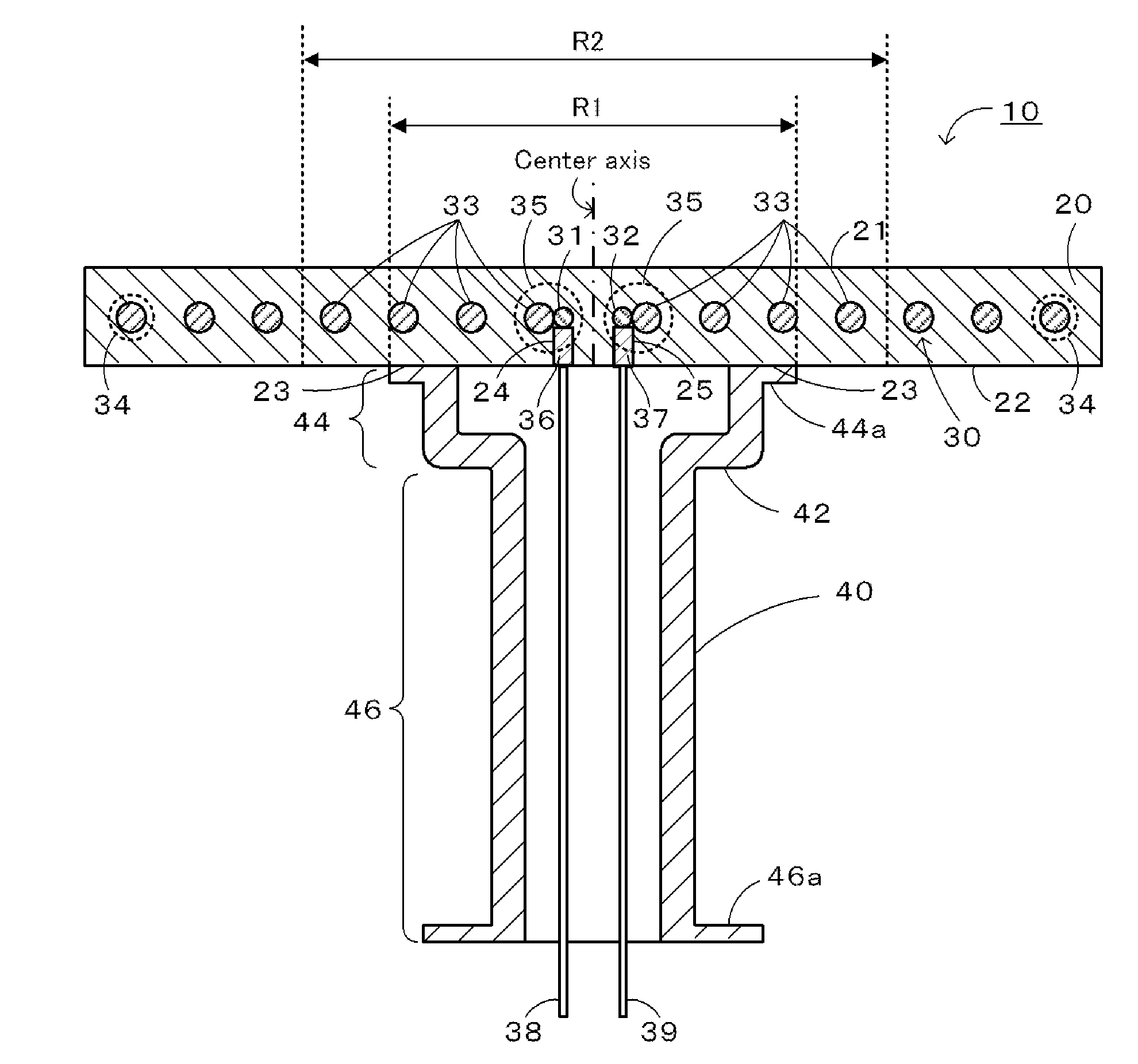
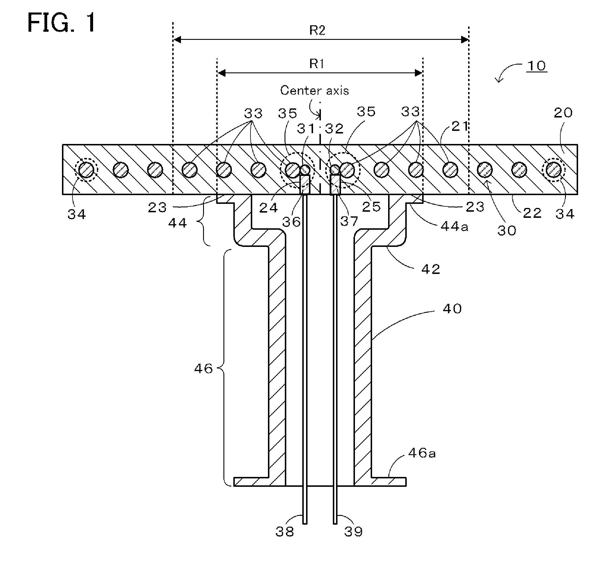
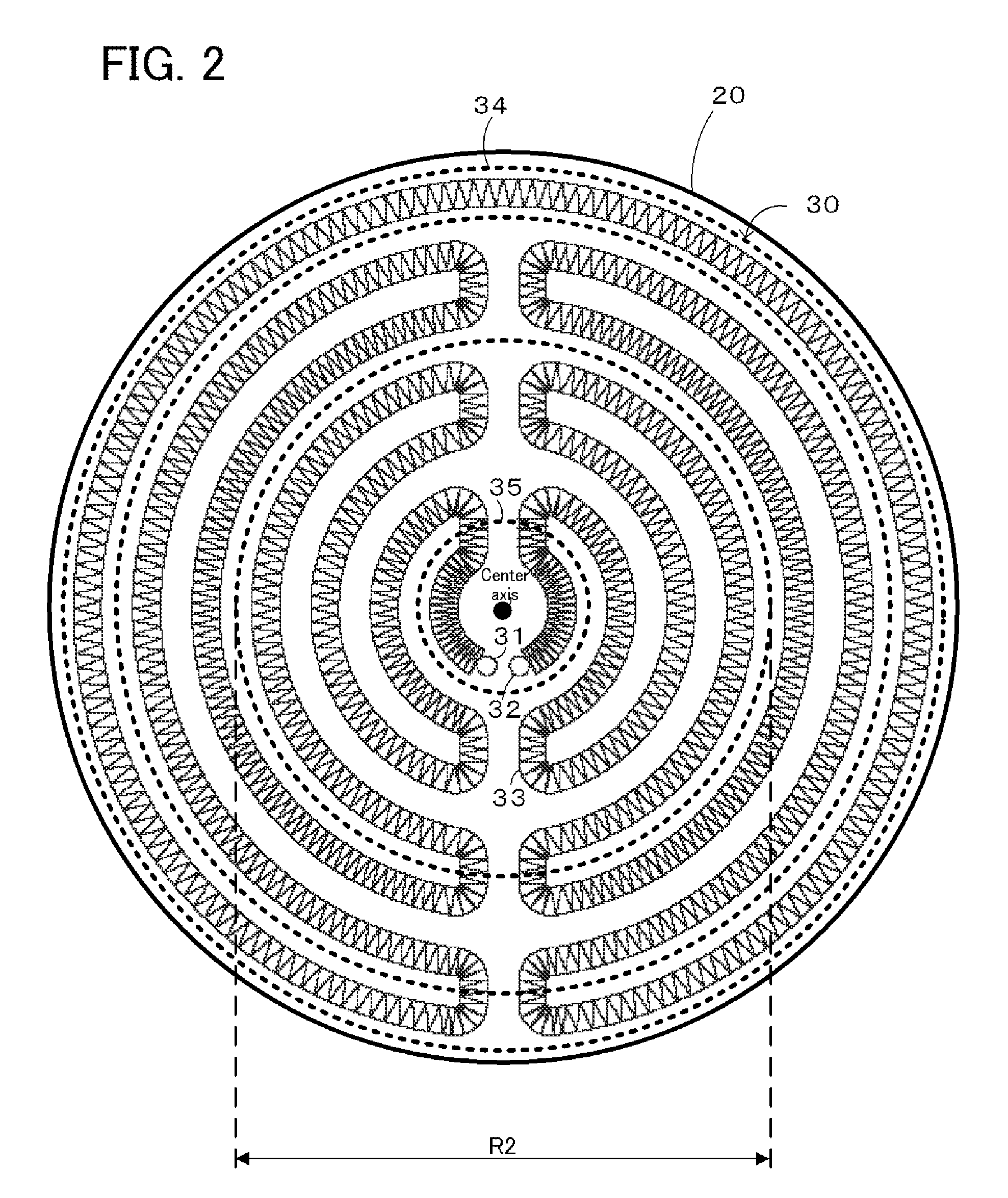
[0059]In Example 1, a specific example corresponding to the ceramic heater 10 of the embodiment shown in FIGS. 1 and 2 was made by a method illustrated in FIG. 3. In particular, the example was prepared as follows.

[0060]First, the ceramic plate 20 was prepared. To 30 parts by weight of aluminum nitride powder (99.5° purity) containing 5 wt % yttria, 0.5 parts by weight polyvinyl alcohol serving as an organic binder and 100 parts by weight water were mixed to prepare a slurry. The slurry was spray-dried to prepare a powder A. A powder B was prepared in the same manner but with a slurry containing the organic binder in an amount 30 times larger. The prepared powders A and B were chemically analyzed to investigate the carbon content. The carbon content was 0.1 wt % in the powder A and 3 wt % in the powder B. Next, the powder A was laid in a die having an inner diameter of 350 mm and a recess was formed by pressing the powder with a die having a diameter of 350 mm and a middle portion (...

example 2

[0062]In Example 2, the ceramic heater 10 was prepared as in Example 1 except that a powder D was used instead of the powder B of Example 1. The powder D was prepared by mixing 30 parts by weight aluminum nitride powder (99.5 purity) containing 5 wt % yttria with 1 part by weight carbon black, 0.5 parts by weight polyvinyl alcohol serving as an organic binder, and 100 parts by weight water to make a slurry, and spray-drying the slurry to prepare a granular powder (referred to as powder D hereinafter). The carbon content in the powder D was 3.4 wt %.

example 3

[0063]In Example 3, a specific example corresponding to a ceramic heater 110 of an embodiment made by the method illustrated in FIG. 4 was prepared. In particular, the example was made as follows.

[0064]First, to 30 parts by weight of aluminum nitride powder (99.5% purity) containing 5 wt % yttria, 4 parts by weight polyvinyl alcohol serving as an organic binder and 100 parts by weight water were mixed to prepare a slurry. The slurry was spray-dried to prepare a granular powder as powder C. The carbon content in the powder C was 0.8 wt %. The powder C was laid in a die to form a disk having a thickness of 15 mm and a flat surface. Then a ring-shaped molybdenum mesh 60a (a metal mesh sheet prepared by interweaving molybdenum wires having a diameter of 0.12 mm) having an outer diameter of 325 mm and an inner diameter of 120 mm was placed in a die in a concentric manner. The powder C was further laid thereon to a thickness of about 1 mm and pressed with a groove-forming die identical to...


PUM

PropertyMeasurementUnit
diameteraaaaaaaaaa
diameteraaaaaaaaaa
diameter R1aaaaaaaaaa

Abstract

A resistive heating element 30 has a higher molybdenum carbide content in a central portion 35 than in a peripheral portion 34. Since molybdenum carbides have a low temperature coefficient of resistance compared to molybdenum, the amount of heat generated in the central portion 35 of the resistive heating element 30 does not increase as much as in the peripheral portion 34 even when the temperature is increased, and the increase in difference in temperature between the peripheral portion 34 and the central portion 35 can be suppressed. In other words, generation of hot spots near the center can be suppressed and a good uniform heating property in a wide range of operation temperatures can be obtained.

Description

BACKGROUND OF THE INVENTION[0001]1. Field of the Invention[0002]The present invention relates to a method for manufacturing a ceramic heater and to a ceramic heater.[0003]Heretofore, ceramic heaters used for heating wafers have been known. Such ceramic heaters are required to have uniform heating property so that the heaters can heat wafers uniformly. For example, Patent Document 1 discloses a ceramic heater including a resistive heating element composed of molybdenum and buried in a ceramic plate composed of aluminum nitride, and an aluminum nitride shaft joined to the plate, wherein the amounts of metal carbides in the resistive heating element are reduced to reduce the non-uniformity in the amounts of carbides among positions of the resistive heating element and to thereby decrease the temperature distribution in the heating surface.[0004]2. Prior Art Documents[0005][Patent Document 1] Japanese Unexamined Patent Application Publication No. 2003-288975.SUMMARY OF THE INVENTION[000...

Claims


Application Information

Patent Timeline
Patent Type & Authority Applications(United States)
IPC IPC(8): H05B3/06H01C17/02
CPCH05B3/143Y10T29/49094Y10T29/49092Y10T29/49083Y10T29/49082Y10T29/49099
Inventor AKATSUKA, YUJIGOTO, YOSHINOBU
Owner NGK INSULATORS LTD
Why Eureka
Try Eureka