Heating glass and manufacturing method thereof

a manufacturing method and glass technology, applied in the field of heating glass, can solve the problems of inability to manufacture glass at low cost, hinder the generalization of heating glass, and inability to achieve heating performance suitable for removing frost and dew condensation at a low voltage, and achieve excellent heating performance and uniform heating performan

Active Publication Date: 2012-11-22
LG CHEM LTD
View PDF13 Cites 11 Cited by
  • Summary
  • Abstract
  • Description
  • Claims
  • Application Information

AI Technical Summary

Benefits of technology

[0009]According to the exemplary embodiments of the present invention, there are provided a heating glass having excellent heating performance at a low voltage and exhibiting uniform heating performance to an entire area of glass so that a thermal conductive pattern is not well visible, an infrared ray (IR) blocking function is ensured, and frost and dew condensation are easily removed, and a method of manufacturing the same.

Problems solved by technology

However, since a manufacturing process is complicated and a material is seriously wasted in the aforementioned method, the glass cannot be manufactured at low cost, thus hindering generalization of the heating glass.
Further, in the case of glass on which TCO (transparent conductive oxide) such as ITO (indium tin oxide) is deposited, there is a problem in that heating performance suitable to remove frost and dew condensation at a low voltage is not implemented.

Method used


Image

  • Heating glass and manufacturing method thereof
  • Heating glass and manufacturing method thereof
  • Heating glass and manufacturing method thereof

Examples


example 1

[0067]The FTO glass (surface resistance: 15 Ω / square), on a surface of which the fluorine tin oxide layer was formed, was prepared. Further, the silver paste was prepared by dissolving 80% of silver particles having the particle diameter of 2 μm, 5% of polyester resin, and 5% of glass frit in 10% BCA (butyl carbitol acetate) solvent.

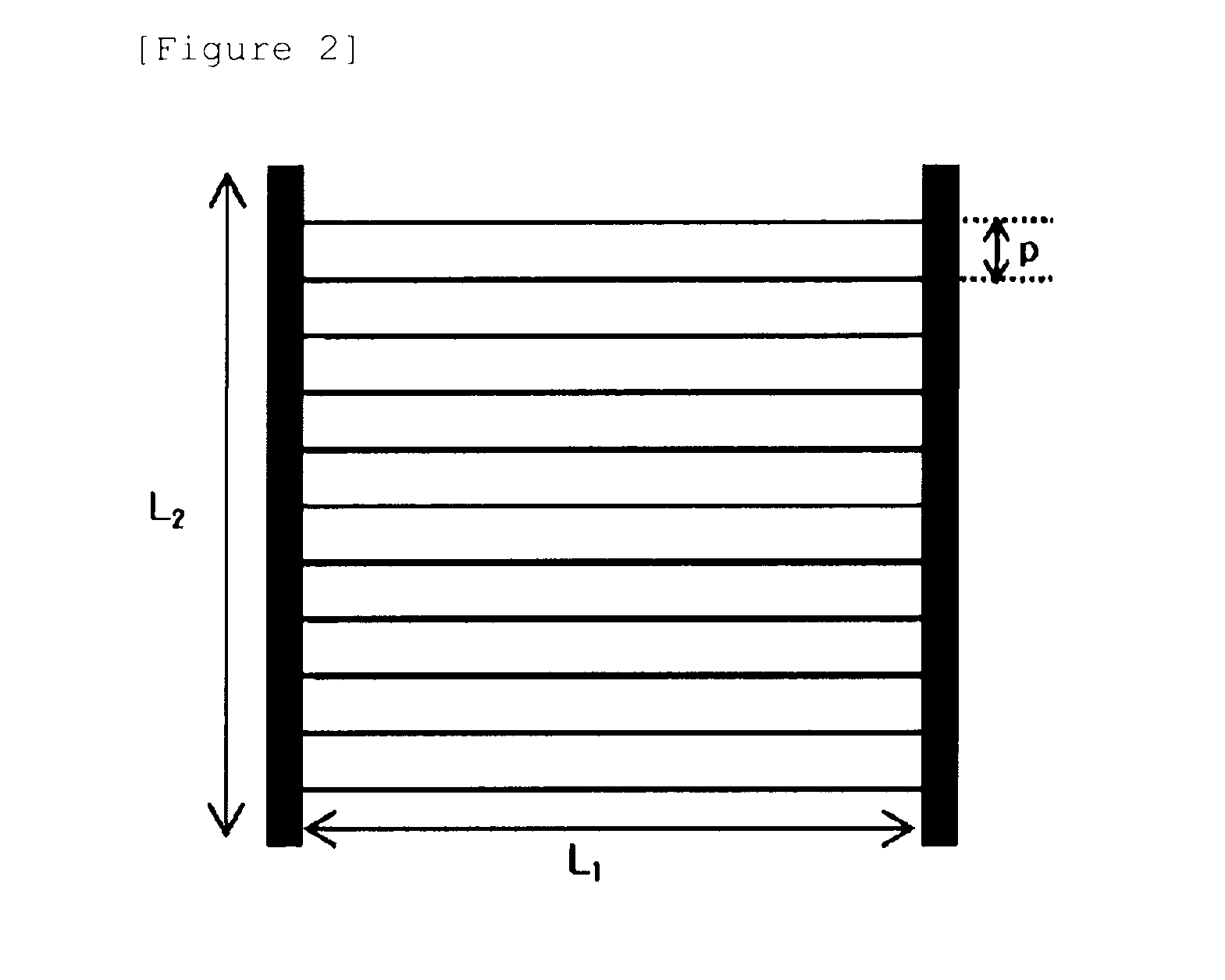
[0068]In addition, the glass having the grid type pattern formed to have the interval of 300 μm, the width of 20 μm, and the depth of 10 μm and have the right angle was prepared as the flat plate for printing.

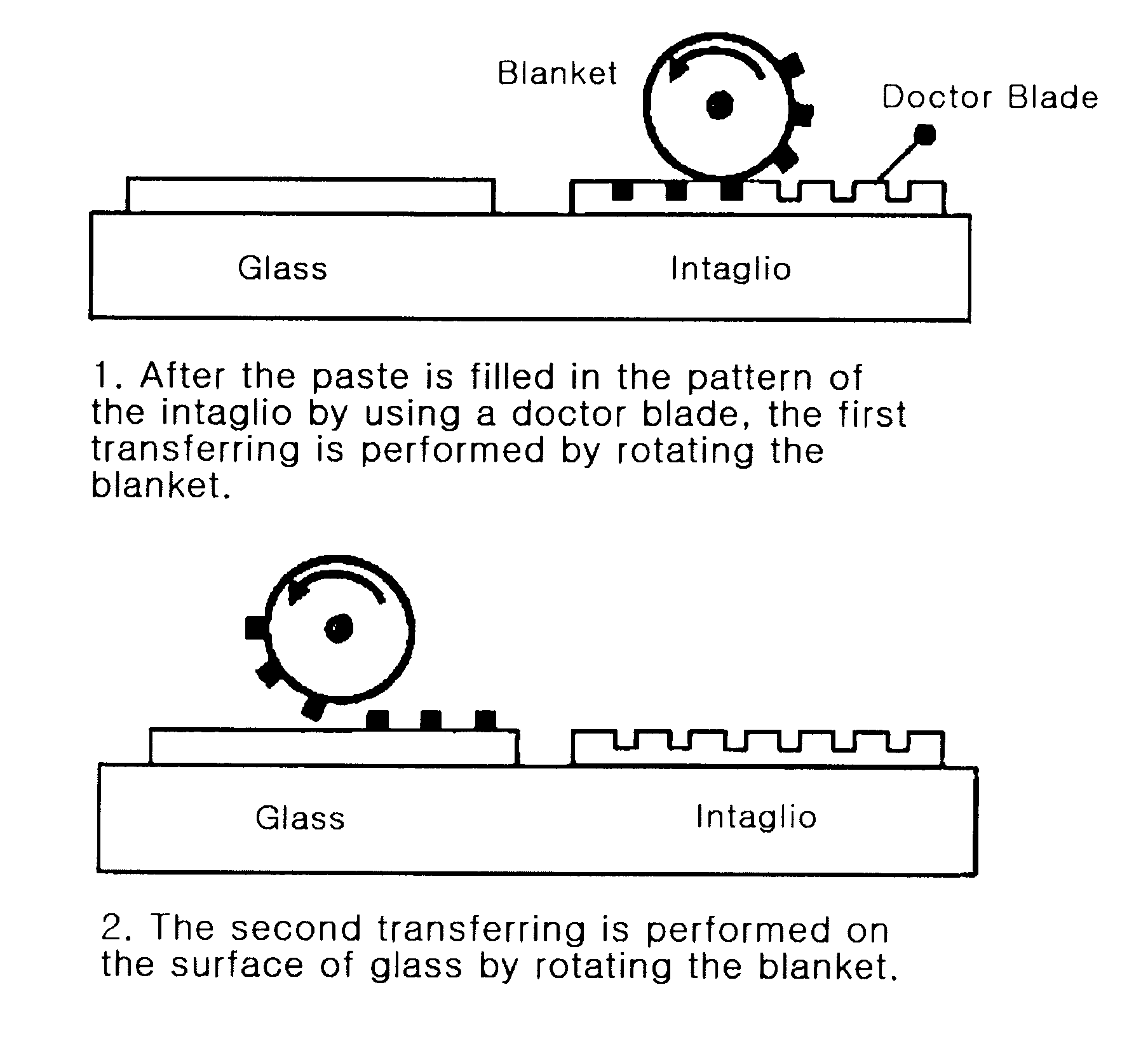
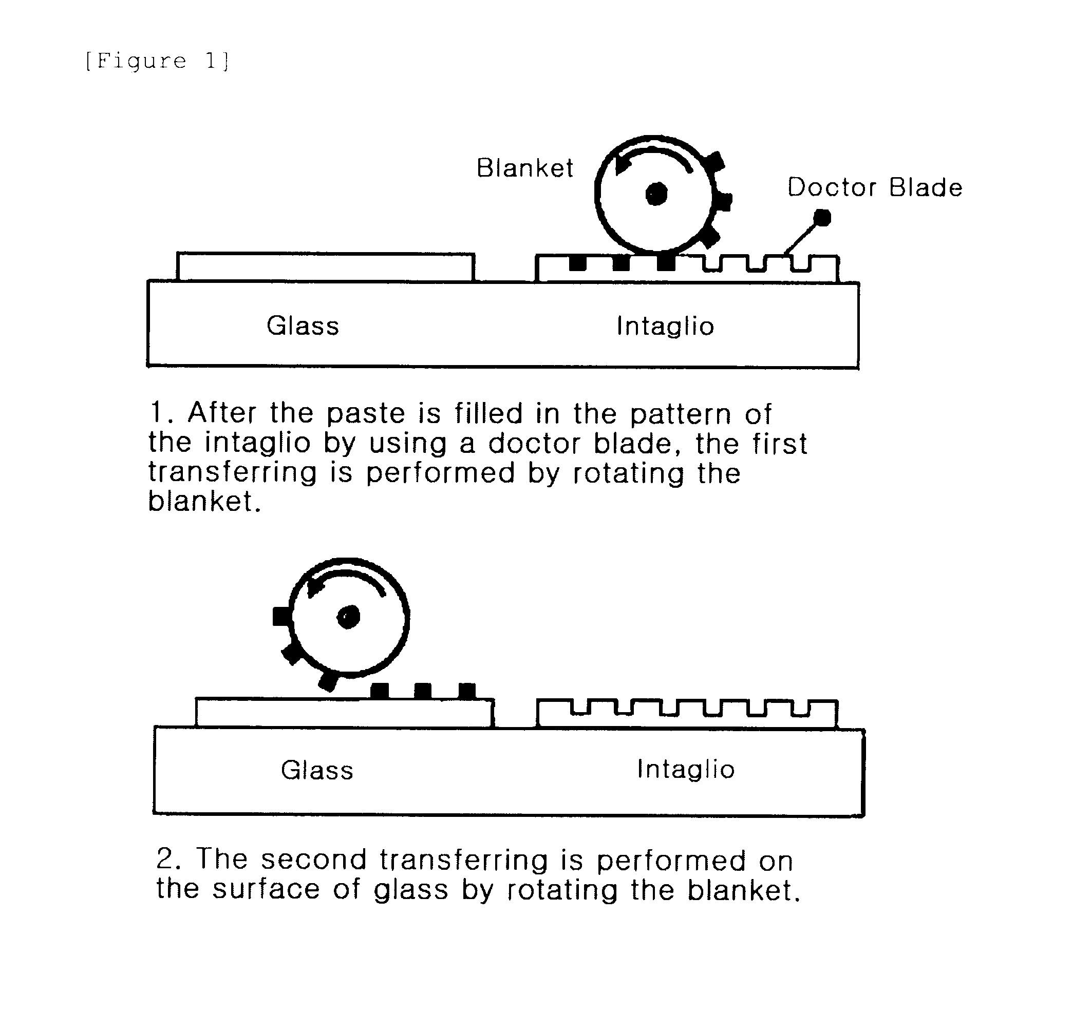
[0069]Next, the grid type silver thermal conductive pattern was formed on the surface of the FTC glass FTO layer by using the offset printer, and then fired at 650° C. for 3 min to form the silver thermal conductive pattern. In this case, the interval between the lines of the formed silver thermal conductive pattern was 300 μm, the line width was 25 μm, the height of the line was 1.5 μm, and the opening ratio was 84%.

experimental example

Driving Voltage

[0072]The bus bar was formed by bringing the copper strip into contact with the heating glass manufactured in Example 1 and Comparative Example 1 by using the clip. Thereafter, the voltage when the heating glass had the heating value of 400 W / cm2 was measured, and is described in the following Table 1.

TABLE 1Voltage when a heating value is 400 W / cm2Example 110 VComparative Example 175 V

[0073]As shown in the aforementioned result, it can be seen that the heating glass according to the present invention exhibits the high heating value even at a low voltage.

[0074]IR Blocking Test

[0075]Transmittances of the heating glass manufactured in Example 1 and Comparative Example 2 were measured by using the spectrometer in a wavelength region of 300 to 2500 nm, and the results are shown in FIGS. 3 and 4.

[0076]As shown in the results, it can be seen that transmittance of the heating glass according to the present invention is reduced in the region of 900 nm or more, but transmittan...


PUM

PropertyMeasurementUnit
thicknessaaaaaaaaaa
heightaaaaaaaaaa
heightaaaaaaaaaa

Abstract

The present invention provides a heating glass including a glass; a transparent conductive oxide (TCO) layer formed on one surface of the glass; and a thermal conductive pattern formed on the transparent conductive oxide layer, and a method of manufacturing the same.

Description

TECHNICAL FIELD[0001]The present invention relates to a heating glass and a method of manufacturing the same, and more particularly, to a heating glass having excellent heating performance at a low voltage and exhibiting uniform heating performance to an entire area of glass so that a thermal conductive pattern is not well visible and frost and dew condensation are easily removed, and a method of manufacturing the same. This application claims priority from Korean Patent Application No. 10-2010-0002494 filed on Jan. 12, 2010, in the KIPO, the disclosure of which is incorporated herein by reference in its entirety.BACKGROUND ART[0002]During the winter or on a rainy day, frost is formed on a glass surface of a vehicle because of a difference between temperatures of the outside and inside of the vehicle. In addition, in the case of an indoor ski resort, a freezing phenomenon occurs because of a difference between temperatures of the inside where there is a slope and the outside of the ...

Claims


Application Information

Patent Timeline
Patent Type & Authority Applications(United States)
IPC IPC(8): H05B3/84B32B37/14B05D5/12
CPCB41M1/06B41M1/10B41M1/12B41M1/34C03C17/36Y10T156/10C03C17/3673C03C2217/94H05B3/84H05B2203/017C03C17/3607G09F13/0413G09F13/22G09F2013/189G09F2013/222G09F13/0422G09F13/0445G09F13/0481Y10S362/812
Inventor KIM, SU-JINCHOI, HYEONKIM, KI-HWANHONG, YOUNG-JUNHWANG, IN-SEOKLEE, DONG-WOOKCHUN, SANG-KI
Owner LG CHEM LTD
Why Eureka
Try Eureka