Experimental device used for thermal fatigue of turbine blade material

An experimental device and turbine blade technology, which is applied to measurement devices, analytical materials, instruments, etc., can solve the problems of inability to obtain key information of samples in real time, high labor and material resources consumption, and inability to achieve rapid changes, and achieve easy process automation. Control, wide range of industry adaptability, no fuel transport effect

Inactive Publication Date: 2019-01-22
NANCHANG HANGKONG UNIVERSITY
View PDF6 Cites 10 Cited by
  • Summary
  • Abstract
  • Description
  • Claims
  • Application Information

AI Technical Summary

Problems solved by technology

Although these methods can simulate the experimental environment with high heat load, they consume a lot of manpower and material resources, require high experimental equipment, and lack or cannot obtain the key information of the sample in real time; in addition, due to the limitation of the heating method, many test devices cannot To achieve a rapidly changing thermal load environment, how to economically and effectively characterize the thermal fatigue failure behavior of high-temperature components through the design of relevant test devices and simulation tests will be a realistic engineering problem that researchers directly face

Method used


Image

  • Experimental device used for thermal fatigue of turbine blade material
  • Experimental device used for thermal fatigue of turbine blade material
  • Experimental device used for thermal fatigue of turbine blade material

Examples


Embodiment Construction

[0024] The preferred embodiments of the present invention will be described in detail below in conjunction with the accompanying drawings, so that the advantages and features of the present invention can be more easily understood by those skilled in the art, so as to define the protection scope of the present invention more clearly.

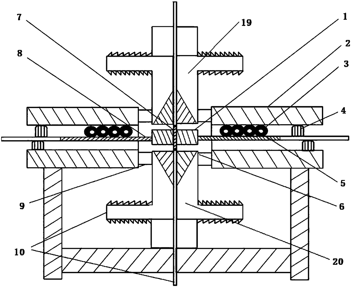
[0025] see figure 1 , figure 2 , image 3 , Figure 4 , an experimental device for thermal fatigue of turbine blade materials, including an induction coil heating system, a temperature test acquisition system, a cooling system, and a test control platform;

[0026] The induction coil heating system adopts a two-way surround heating method with a symmetrical structure, including a special induction coil (2) and an AC power supply. The heating range of the induction coil (2) is 25°C-1200°C, and the heating temperature per second can reach 50°C- 100°C, the induction coil (2) can be made into different shapes according to the different sizes of t...


PUM

PropertyMeasurementUnit
radiusaaaaaaaaaa

Abstract

The invention discloses an experimental device used for the thermal fatigue of a turbine blade material. The device comprises an experiment test bench, an induction coil heating system, a temperaturetesting and collecting system, a cooling system and an experiment control platform, wherein the induction coil heating system, the temperature testing and collecting system, the cooling system and theexperiment control platform are independently connected with the experiment test bench; a specimen is fixed on a fixture; cooling gas passes through a first cooling gas channel and a second cooling gas channel to cool the surface, the end part and the inner side of the specimen; a thermocouple is independently arranged on a position with a surface radius of 3.5mm, a position with a surface radiusof 6.5mm, a position with a surface radius of 8.5mm and a specimen inner ring; the thermocouple is connected with a temperature display instrument and a computer host; and the inner ring of the induction coil is provided with an induction coil cooling water channel, cooling water flows in from one side of the induction coil and flows out from the other side. The device has the advantages that thermal fatigue working environment, where the turbine blade is positioned, with alternating circulation under different working states can be simulated, and in addition, important experiment data can beprovided for the thermal fatigue failure mechanism and the reliability of the turbine blade material.

Description

technical field [0001] The invention relates to the field of high-temperature component detection equipment, in particular to an experimental device for thermal fatigue of turbine blade materials. Background technique [0002] In recent years, due to the urgent need for the development of aerospace materials, the traditional thermal fatigue test methods and test conditions are simple and provide little information, which cannot meet the growing needs of modern scientific research. The problem of thermal damage to materials caused by high heat load has become increasingly prominent, which has attracted great attention from research institutions in various countries, and established corresponding heating methods based on laser heating, quartz lamps, high-temperature radiation, resistance heaters, and high-temperature combustion gas. Experimental platform for thermal fatigue experimental research. Although these methods can simulate the experimental environment with high heat ...

Claims


Application Information

Patent Timeline
Patent Type & Authority Applications(China)
IPC IPC(8): G01N3/60G01N3/02
CPCG01N3/02G01N3/60
Inventor 胡晓安张宇赵高乐张强吴锦武
Owner NANCHANG HANGKONG UNIVERSITY
Why Eureka
Try Eureka