Underground composite heater for in-situ development of underground mineral products

A heater, in-situ technology, applied in the fields of production fluids, wellbore/well components, earthwork drilling, etc., can solve problems such as narrow application range, inability to apply to formations, and inability to meet the requirements of different types of unconventional oil and gas resource extraction, etc. achieve the effect of guaranteeing normal operation

Active Publication Date: 2022-07-29
JILIN UNIV
View PDF8 Cites 0 Cited by
  • Summary
  • Abstract
  • Description
  • Claims
  • Application Information

AI Technical Summary

Problems solved by technology

However, since the combustion gas is mainly hydrocarbon gas, the supporting gas is mainly air or oxygen; therefore, the main components of the high-temperature tail gas produced by combustion are high-temperature water vapor and carbon dioxide; due to the different physical properties of unconventional oil and gas resources, the , it is necessary to select different injection gases; taking oil shale as an example, chemical reactions need to occur in the process of oil shale thermal recovery, and different types of gases will affect the cracking behavior of organic matter inside oil shale, and will also affect the product composition, so it is necessary to Select injection gas according to the nature of the formation; combustion and heating can only inject high-temperature water vapor and carbon dioxide into the formation, which cannot be applied to a wider range of formations; therefore, the application range is narrow and cannot meet the needs of different types of unconventional oil and gas resources. Require

Method used


Image

  • Underground composite heater for in-situ development of underground mineral products
  • Underground composite heater for in-situ development of underground mineral products
  • Underground composite heater for in-situ development of underground mineral products

Examples


Embodiment Construction

[0019] In order to make those skilled in the art better understand the technical solutions of the present invention, the technical solutions in the embodiments of the present invention will be clearly and completely described below with reference to the accompanying drawings in the embodiments of the present invention. Obviously, the described The embodiments are only some of the embodiments of the present invention, but not all of the embodiments.

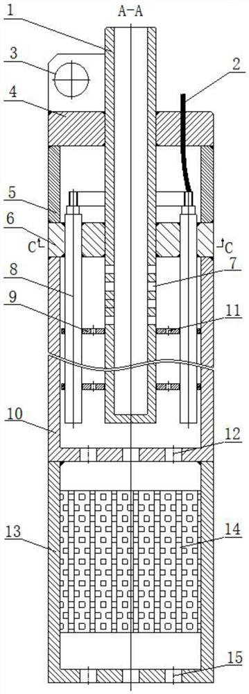
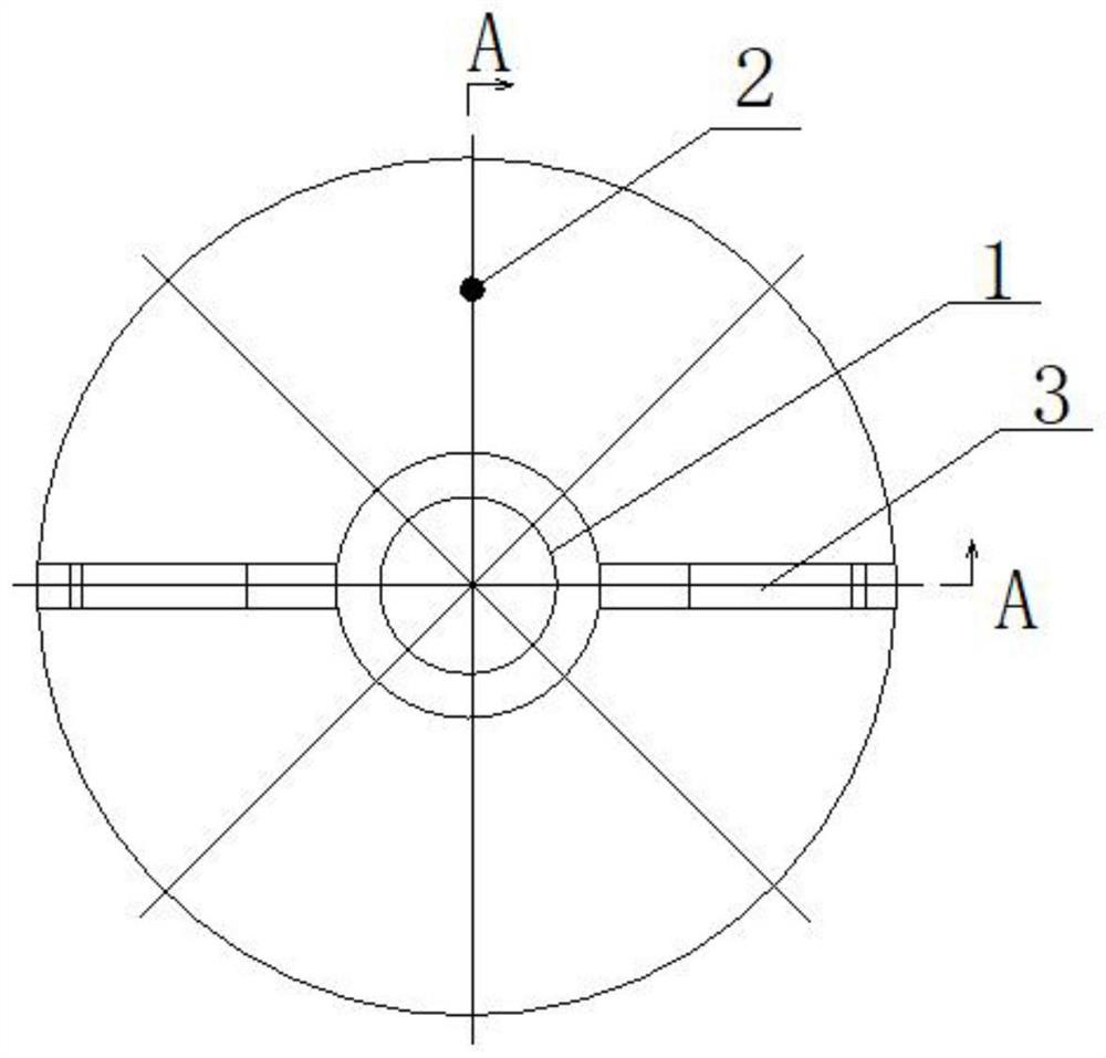
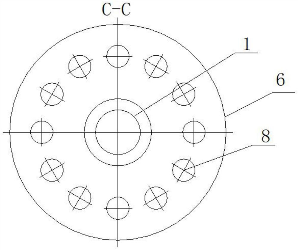
[0020] figure 1 A schematic diagram of the structure of a downhole composite heater used for in-situ development of underground minerals is shown; figure 2 A top view of a downhole composite heater for in-situ development of underground minerals is shown, i.e. figure 1 The A-A rotated cross-sectional view; image 3 The cross-sectional view of the lower cover plate of the cable compartment in the downhole composite heater used for the in-situ development of underground minerals is shown, that is, figure 1 C-C sectional view of ...


PUM


Abstract

An underground composite heater for in-situ development of underground mineral products belongs to the field of underground heating exploitation of unconventional oil and gas resources and comprises a gas injection pipe, a cable, a cable bin, an electric heating rod, a baffle plate, a heater upper pipe body, a heater lower pipe body and porous foamed aluminum. A baffle plate vent hole is formed in the baffle plate, a second air outlet is formed in the bottom of the heater upper pipe body, a third air outlet is formed in the bottom of the heater lower pipe body, and the first air outlet, the electric heating rod, the baffle plate, the heater upper pipe body, the baffle plate vent hole and the second air outlet jointly form an electric heating part. The lower pipe body of the heater, the porous foamed aluminum loaded with the catalysts platinum, rhodium and palladium and the third gas outlet form a combustion heating part, the two functions of electric heating and combustion heating are integrated into the functions of one heater, and the exploitation requirements of different types of unconventional oil and gas resources such as oil shale, thickened oil, tight oil and natural gas hydrates can be met.

Description

technical field [0001] The invention relates to an underground composite heater for in-situ development of underground minerals, which is suitable for underground heating and exploitation of unconventional oil and gas resources such as oil shale, heavy oil, tight oil and natural gas hydrate. Background technique [0002] Unconventional oil and gas resources such as oil shale, heavy oil, tight oil and natural gas hydrate are important strategic resources, and countries around the world have vigorously carried out relevant research in order to achieve breakthroughs in the field of unconventional oil and gas resource extraction. The exploitation of unconventional oil and gas resources such as oil shale, heavy oil, tight oil and natural gas hydrate is considered to be the most effective method by in-situ heating downhole. The key to the regulation of oil and gas resource extraction. [0003] At present, there are two main heating methods for downhole heaters. One is electric he...

Claims


Application Information

Patent Timeline
Patent Type & Authority Applications(China)
IPC IPC(8): E21B43/24
CPCE21B43/24E21B43/2401
Inventor 王元曲莉莉李强
Owner JILIN UNIV
Why Eureka
Try Eureka