
Waste grease collecting box, collecting system, grease replacing system and waste grease collecting box cleaning method

A collection system and collection box technology, applied in the field of waste grease collection box, can solve the problems of increased abrasive particles, laboriousness, space occupation, etc., and achieve the effects of high space utilization, time saving, and convenient cleaning

Pending Publication Date: 2022-07-29
AUTOL TECH
View PDF0 Cites 0 Cited by
  • Summary
  • Abstract
  • Description
  • Claims
  • Application Information

AI Technical Summary

Problems solved by technology

[0002] In the wind power industry, in order to ensure the good operation of the pitch bearing of the fan, it is necessary to regularly add grease to the pitch bearing. After a period of use, the abrasive particles generated by the internal friction of the bearing will increase, and the grease in the bearing will become waste grease. If it cannot be cleaned in time, it will affect the service life of the bearing, and even cause a safety accident in severe cases.
[0003] In this regard, the bearings in the wind power industry are currently equipped with a waste grease collection system to collect waste grease. The waste grease collection system generally includes a grease suction and discharge device installed on the grease discharge port of the bearing. Each grease suction and discharge device is connected to a corresponding The waste grease collection bottle or waste grease collection bag is used to store the waste grease collected from the grease suction and discharge device. Due to the limitation of space and installation structure, the waste grease collection bottle and waste grease collection bag are limited in size and need to be replaced frequently, but Because there are many grease outlets on the blower, and there are many grease suction and discharge devices installed, it is more laborious to install or replace the waste grease collection bottle, especially the replacement operation in the blower is not only time-consuming, but also very laborious; On the other hand, due to the limited size of waste fat collection bottles and waste fat collection bags, it is very difficult to clean up. In the existing methods, the waste fat collection bottles or bags are generally not cleaned after being removed, but directly piled up, resulting in space occupation and environmental pollution. The problem of pollution, waste fat collection bottles and bags are no longer reused, resulting in a lot of waste of materials, and the disposal of waste fat after collection has become a difficult problem in the industry
[0004] And there is also an attempt to pass the waste fat sucked by a plurality of fat suction and discharge devices into a large box or a large bag together on the market, but when the waste fat is sucked by the fat suction and discharge device, a large amount of air is contained in the waste fat, and the waste fat and The gas ratio is not lower than 1:1, even up to 1:5, that is, for every 1 unit of waste fat collected, 5 units of gas will be collected at the same time, and most of the 5 units of gas are trapped in the waste fat, taking up a lot of space. Volume, in order to meet the purpose of replacing the waste grease collection container on the fan at least half a year, it is necessary to set up a very large waste grease collection container, which leads to a series of problems such as large space occupation, difficulty in layout, and difficulty in replacement and cleaning

Method used


Image

  • Waste grease collecting box, collecting system, grease replacing system and waste grease collecting box cleaning method
  • Waste grease collecting box, collecting system, grease replacing system and waste grease collecting box cleaning method
  • Waste grease collecting box, collecting system, grease replacing system and waste grease collecting box cleaning method

Examples


Embodiment approach

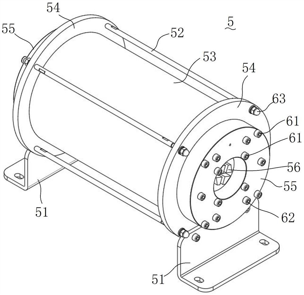
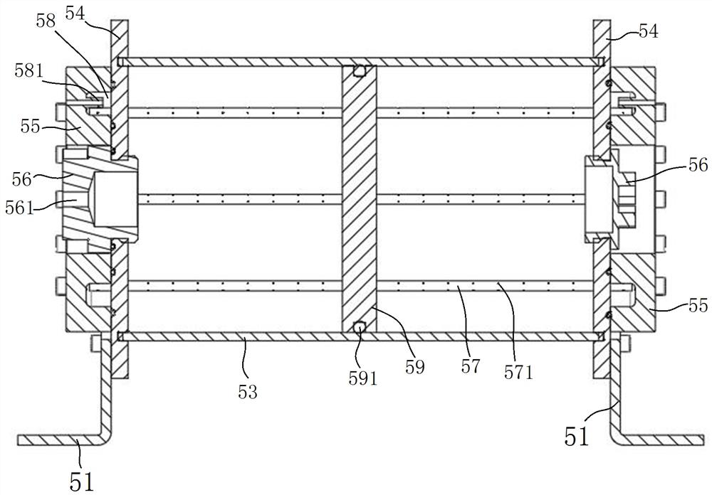
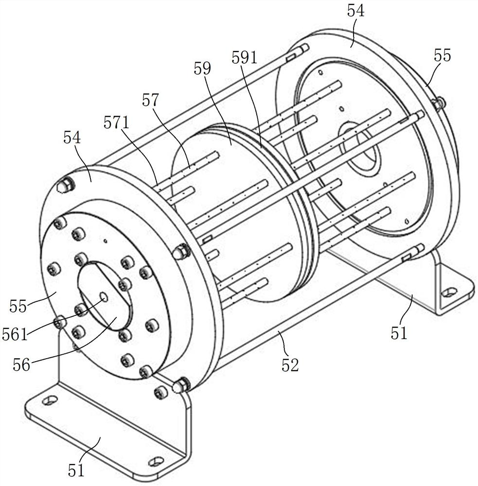
[0081] An embodiment of the waste fat collection system of the present invention: as Figure 7 The schematic diagram of the waste grease collection system is shown. Taking the fan pitch bearing as an example, the main components of the waste grease collection system are the grease suction and discharger 3 and the drive device. Figure 7 In order to control the dual oil circuits to drive a plurality of grease suction and discharge devices 3 to work, the grease suction and discharge devices 3 are installed at each grease discharge hole of the pitch bearing, that is, a plurality of grease suction and discharge devices 3 are arranged around each pitch bearing. In other embodiments Among them, an electric fat suction and discharge device 3 can also be used, and each fat suction and discharge device 3 of the electric fat suction and discharge device 3 has an independent motor as the power, and the volume is small. The waste grease collection box 5 is detachably installed on the hub,...


PUM


Abstract

The invention relates to a waste grease collecting box, a collecting system, a grease changing system and a waste grease collecting box cleaning method, which can reduce the gas content in waste grease, reduce the volume of a waste grease collecting container and facilitate the cleaning of the waste grease. Comprising a box body, a grease inlet and a grease outlet are formed in the box body, a cavity for containing waste grease is formed in the box body, at least one exhaust pipe is arranged in the cavity, a plurality of small holes for exhausting and discharging base oil separated from the waste grease are formed in the exhaust pipe, the exhaust pipe is communicated with the external atmosphere through an exhaust channel formed in the box body, and the exhaust pipe is further communicated with the cavity through the small holes. The exhaust passage is provided with an oil collecting cavity for collecting base oil flowing out of the exhaust pipe, the oil collecting cavity is divided into an air cavity and an oil cavity, the exhaust pipe is communicated into the air cavity, the air cavity is further provided with an air outlet for discharging air in the oil collecting cavity, and after waste grease enters the cavity from the grease inlet, the air in the cavity and the base oil in a segregation state are discharged into the exhaust pipe from the small hole. After base oil and air are introduced into the air cavity from the exhaust pipe, the base oil enters the oil cavity, and the air is exhausted from the air outlet.

Description

technical field [0001] The invention relates to a waste grease collection box, a collection system, a grease replacement system and a method for cleaning the waste grease collection box. Background technique [0002] In the wind power industry, in order to ensure the good operation of the pitch bearing of the wind turbine, it is necessary to regularly add grease to the pitch bearing. After a period of use, the abrasive particles generated by friction in the bearing increase, and the grease in the bearing becomes waste grease. If it cannot be cleaned in time, it will affect the service life of the bearing, and even cause a safety accident in severe cases. [0003] In this regard, at present, a waste grease collection system is installed on the bearings of the wind power industry to collect waste grease. The waste grease collection system generally includes a grease suction and discharge device installed on the grease discharge port of the bearing. Each grease suction and disc...

Claims


Application Information

Patent Timeline
Patent Type & Authority Applications(China)
IPC IPC(8): F16N31/02F16C33/66F03D80/70
CPCF16N31/02F16C33/6622F03D80/70F16N2210/025F16N2210/14F16C2360/31
Inventor 刘新功赵大平
Owner AUTOL TECH
Learn More