Near-to-eye display equipment and imaging method thereof

A near-eye display and equipment technology, applied in the field of optics, can solve problems such as difficulty in realizing super-large field of view display, complex optical structure, and large image distortion, and achieve the effect of small image distortion, simple optical structure, and long exit pupil distance

Pending Publication Date: 2022-07-29
SHENZHEN DETYL OPTOELECTRONICS CO LTD
View PDF0 Cites 0 Cited by
  • Summary
  • Abstract
  • Description
  • Claims
  • Application Information

AI Technical Summary

Problems solved by technology

[0002] In recent years, with the development of micro-display, optical hardware and software technology, near-eye display products emerge in an endless stream, and its application in the entertainment industry, virtual reality and other fields is becoming more and more extensive; the near-eye display devices in the prior art often have optical Complex structure, poor optical performance, difficult to achieve super large field of view display, large image distortion in real environment, etc., so that users often experience dizziness, nausea, and even vomiting when using it

Method used


Image

  • Near-to-eye display equipment and imaging method thereof
  • Near-to-eye display equipment and imaging method thereof

Examples


Embodiment 1

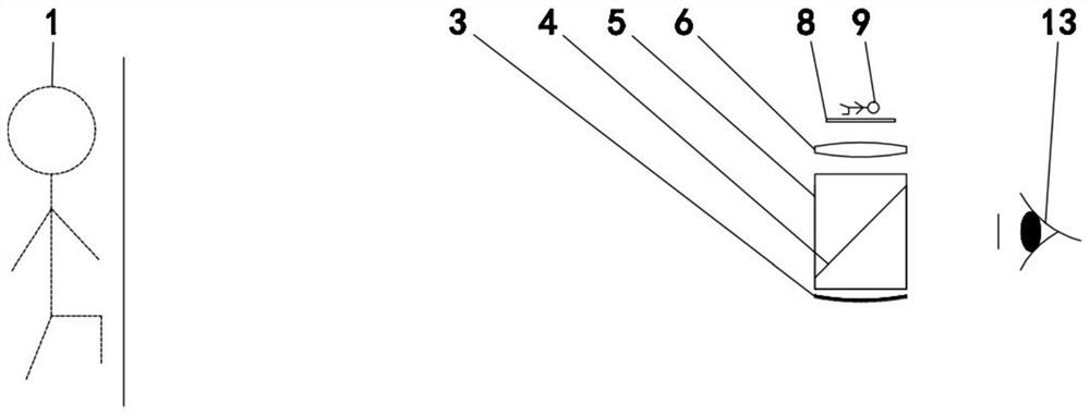
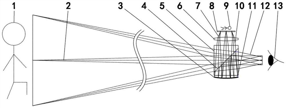
[0025] A near-eye display device such as figure 1 and figure 2 As shown, it includes: a set of image display screen unit 8 for displaying image 9, a set of optical lens set 6 for correcting various optical image points of optical imaging, a set of optical length extension and optical path A set of optical prism group devices 5 for turning, a set of prism beam splitting surface devices 4 for image light splitting and light path turning, and a set of optical reflection devices 3 for image optical reflection and light field compression.

[0026] Further, the image display screen unit 8 may be a common display screen in the market, which is used to display the image to be displayed, which belongs to the prior art and will not be repeated here.

[0027] Further, the optical lens group device 6 is located below the image display screen unit 8, and the optical lens group device 6 is composed of one or more optical elements. The optical elements can be lenses, and the lenses can be ...

Embodiment 2

[0032] An imaging method of a near-eye display device, comprising the following steps:

[0033] Step 1, the image display screen unit 8 displays the required image 9, and the image light enters the optical lens group device 6 to correct the optical image point of the optical imaging to form a corrected image light 10;

[0034] Step 2: After the corrected image light 10 enters the optical prism assembly device 5, the optical path is increased to form the extended image light 11;

[0035] Step 3: After the extended-range image light 11 is internally or externally reflected by the optical reflection device 3, it becomes a parallel light of an image point suitable for human eyes to observe, and the parallel light enters the optical prism group again. device 5;

[0036] Step 4. When the range-extended image light 11 reaches the prism beam splitter device 4, a part of the light rays are reflected by the prism beam splitter device 4 and then pass through the optical prism group devi...

specific Embodiment

[0039] The following is a specific embodiment of the present invention. In this embodiment, the imaging method of the near-eye display device includes the following steps:

[0040] Step 1. Display the image 9 to be displayed on the image display screen unit 8, an optical lens group device 6 is arranged below the image display screen unit 8, and the image light 7 is emitted from the image display screen unit 8, and passes through one or more into the optical lens group device 6 composed of one or more optical elements and then enter the optical prism group device 5 composed of one or more optical elements;

[0041]In step 2, a prism beam splitter device 4 composed of one or more optical elements is arranged inside the optical prism group device 5 , an optical reflection device 3 is arranged below the optical prism group device 5 , and the image light 7 is inside the optical reflection device 3 . Under the action of reflection or external reflection, it becomes light that can be...


PUM


Abstract

The invention discloses a near-eye display device and an imaging method thereof. The near-to-eye display equipment comprises a group of image display screen units used for image display, a group of optical lens group devices used for correcting various optical phase differences of optical imaging, a group of optical prism group devices used for realizing optical path extension and optical path turning, and a group of prism light splitting surface devices used for image light splitting and optical path turning, and a group of optical reflection devices for image optical reflection and light field compression. The whole near-to-eye display device is simple in optical structure, and an ultra-large field-of-view display system is easy to realize; the distance between the image display screen unit and the optical lens group device can be adjusted, so that the diopter can be adjusted more easily; meanwhile, real environment image distortion is small, the structure is close to a coaxial design, the optical performance is good, and the exit pupil distance is long and is more suitable for human eye observation.

Description

technical field [0001] The invention relates to the field of optics, in particular to a near-eye display device and an imaging method thereof. Background technique [0002] In recent years, with the development of microdisplays and optical software and hardware technologies, near-eye display products have emerged one after another, and its applications in the entertainment industry, virtual reality and other fields have become more and more extensive; the near-eye display devices in the existing technology often have optical The complex structure, poor optical performance, difficult to achieve large field of view display, large distortion of the real environment image, etc., so that users often experience dizziness, nausea, and even vomiting during use. SUMMARY OF THE INVENTION [0003] The present invention provides a near-eye display device and an imaging method thereof that can effectively solve the above-mentioned technical problems. [0004] In order to achieve the p...

Claims


Application Information

Patent Timeline
Patent Type & Authority Applications(China)
IPC IPC(8): G02B27/01
CPCG02B27/0101
Inventor 宋建明胡洁
Owner SHENZHEN DETYL OPTOELECTRONICS CO LTD
Why Eureka
Try Eureka