Transformer easy to assemble and position

A transformer and positioning part technology, applied in the field of transformers, can solve problems such as small application range, pin drop-off, and troublesome positioning of magnetic cores, and achieve the effects of ingenious and reasonable structural design, guaranteed strength and stability, and improved connection firmness

Pending Publication Date: 2022-07-29
东莞市慧创电子有限公司
View PDF0 Cites 0 Cited by
  • Summary
  • Abstract
  • Description
  • Claims
  • Application Information

AI Technical Summary

Problems solved by technology

[0003] A traditional transformer is generally composed of a skeleton, a coil and a magnetic core. In the process of producing a transformer, the enameled wire is first wound on the skeleton, and the coil is formed after the enameled wire is wound. Fix it; however, its structural design is not good, and the positioning of the magnetic core on the skeleton is troublesome, which makes the assembly of the magnetic core on the skeleton not firm enough, resulting in instability in the subsequent fixing operation of the magnetic core and the skeleton, which affects the effect of the colloid , the quality is inconsistent, the production cost of the transformer is increased, the production efficiency is low, and the scope of application is small
[0004] In addition, the pins of the transformer are easy to fall off the transformer due to the pulling force, so that the transformer cannot be connected to the PCB board or the connection with the PCB board is not firm, thus affecting the normal use of the transformer, and the use stability is not good.

Method used


Image

  • Transformer easy to assemble and position
  • Transformer easy to assemble and position
  • Transformer easy to assemble and position

Examples


Embodiment Construction

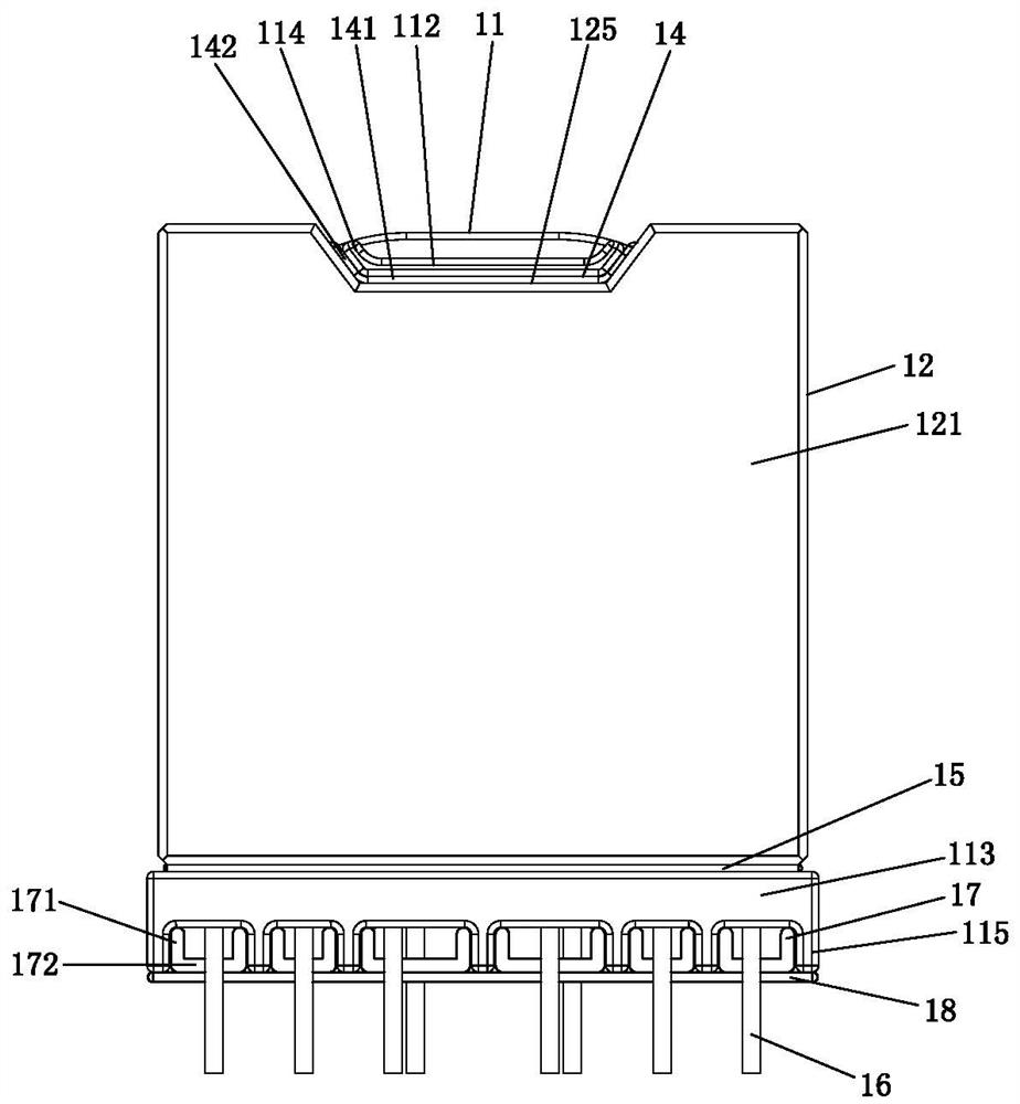
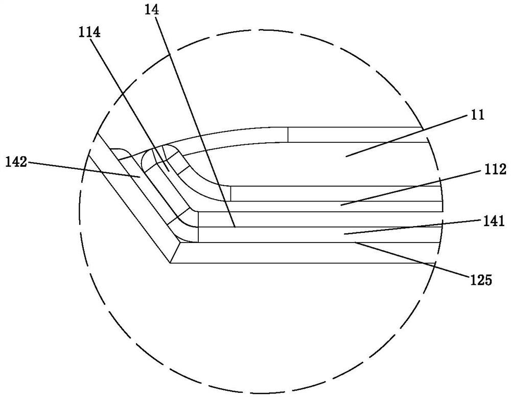
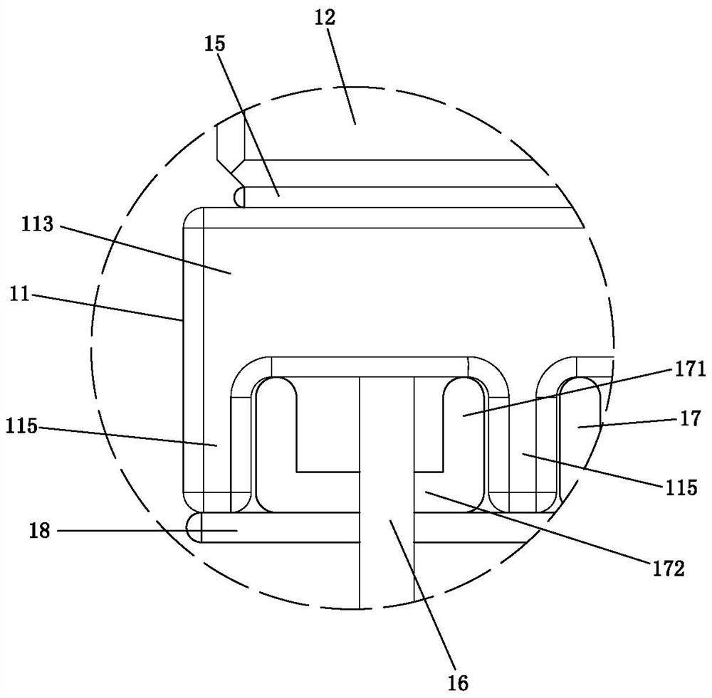
[0036] Please refer to Figure 1 to Figure 6 shown, which show the specific structure of an embodiment of the present invention.

[0037] A transformer that is easy to assemble and locate, comprising a bobbin 11, a magnetic core 12 and a coil (not shown in the figure); wherein:

[0038] The skeleton 11 has a winding slot, and the coil is wound in the winding slot;

[0039] The magnetic core 12 includes two E-shaped magnetic core pieces 121 spliced ​​to each other front and rear, the skeleton 11 is arranged between the two E-shaped magnetic core pieces 121 , and the E-shaped magnetic core piece 121 includes a core body 122 . and the side edges 123 and the center column 124 arranged on the core body, the side edges 123 are respectively arranged on the left and right sides of the core body 122, and the center column 124 is arranged in the middle part of the core body 122 and located on the left and right sides Between the side edges 123 of the skeleton 11 , a through hole 111 i...


PUM


Abstract

The invention discloses a transformer easy to assemble and position. The transformer comprises a framework, a magnetic core and a coil, the magnetic core comprises two E-shaped magnetic core parts which are mutually spliced front and back, the framework is arranged between the two E-shaped magnetic core parts, each E-shaped magnetic core part comprises a core body, a side edge and a middle column, the side edge and the middle column are arranged on the core body, a through hole is formed in the framework, the middle columns of the two E-shaped magnetic core parts are connected through the through hole, and a positioning edge extending towards the core body is arranged at the upper end of the framework. A positioning groove matched with the positioning part is formed in the core body, the positioning part is arranged at the lower end of the framework, and the lower end of the core body is limited by the upper end of the positioning part; thus, through the design of the framework and the magnetic core, the positioning grooves are connected with the positioning edges in a matched mode, and the positioning portions are connected with the lower end of the magnetic core in a matched mode, so that positioning operation of the magnetic core on the framework is achieved, assembling is firm, follow-up operation of fixing the magnetic core and the framework through glue is facilitated, structural design is ingenious and reasonable, and quality is stable and consistent; the production efficiency of the transformer is improved, the cost is low, and the application range is wide.

Description

technical field [0001] The invention relates to the technology in the field of transformers, in particular to a transformer that is easy to assemble and locate. Background technique [0002] With the development of science and technology, the volume of electronic products is getting smaller and smaller, and the volume of magnetic components is also getting smaller and thinner. At present, transformers are indispensable devices in life and industrial production. The existence of transformers is becoming more and more important. While emphasizing functionality, transformers also need to consider structural rationality. The design and use of transformers are particularly important. It can convert AC and high-voltage mains commonly used in external circuits into Low voltage direct current used by some small power devices. [0003] The traditional transformer is generally composed of a skeleton, a coil and a magnetic core. In the process of producing the transformer, the enamele...

Claims


Application Information

Patent Timeline
IPC IPC(8): H01F27/30H01F27/24H01F27/26H01F27/06
CPCH01F27/306H01F27/24H01F27/266H01F27/06H01F2027/065
Inventor 腾云曾昭友韩远雄
Owner 东莞市慧创电子有限公司
Why Eureka
Try Eureka