Output head with Raman filtering function

An output head and connection joint technology, which is applied in the laser field, can solve the problem that the safety of the optical fiber output head needs to be improved, and achieve the effect of simplifying the process and reducing the welding problem.

Pending Publication Date: 2022-07-29
长沙大科光剑科技有限公司
0 Cites 0 Cited by

AI-Extracted Technical Summary

Problems solved by technology

[0006] The invention provides an output head with Raman filtering, which solves ...

Abstract

The invention provides an output head with Raman filtering. The output head with the Raman filtering function comprises a mounting support, an output end, a Raman filter and a Raman filter, wherein the mounting support is provided with an external thread bushing; the heat dissipation mechanism is mounted on the mounting support; and the connecting joint is mounted on the axis of the mounting support, an internal thread bushing is arranged on the connecting joint, and the internal thread bushing is mounted on the external thread bushing in a threaded manner. According to the output head with the Raman filtering function, the Raman grating installed outside the connector is integrally installed between the installation support and the connecting connector, the connecting connector can conveniently filter Raman light reflected by a cable in a closed mode, the Raman light and reflected light can be better filtered, a laser device is safer in use, and the service life of the laser device is prolonged. And the welding problem of a plurality of devices is reduced, so that the process is simplified.

Application Domain

Coupling light guidesActive medium shape and construction +1

Technology Topic

Erbium lasersEngineering +3

Image

  • Output head with Raman filtering function
  • Output head with Raman filtering function
  • Output head with Raman filtering function

Examples

  • Experimental program(2)

Example

[0042] First embodiment:
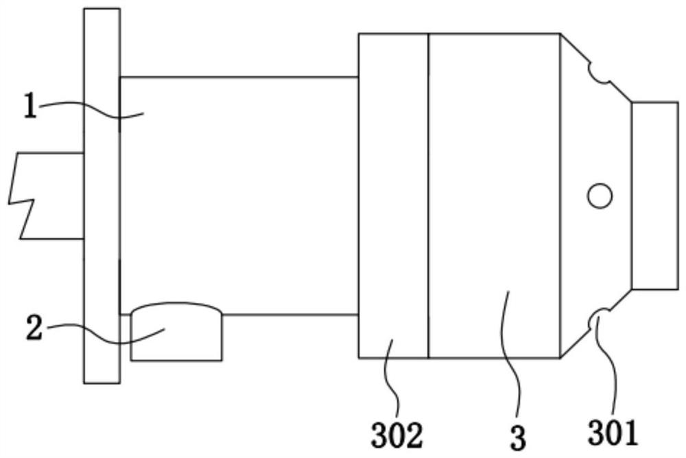
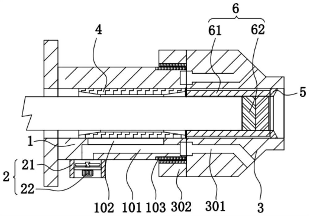
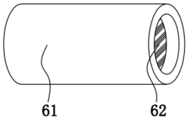
[0043] Please refer to figure 1 , figure 2 and image 3 ,in, figure 1 A schematic structural diagram of the first embodiment of the output head with Raman filtering provided by the present invention; figure 2 for figure 1 The schematic diagram of the overall structure shown; image 3 for figure 2 3D view of the grating mechanism section shown.
[0044] An output head with Raman filtering, comprising:
[0045] The mounting support 1 is provided with an external thread sleeve 103 on the mounting support 1;
[0046] a heat dissipation mechanism 2, the heat dissipation mechanism 2 is installed on the installation support 1;
[0047] The connecting joint 3 is installed on the axis of the mounting support 1 , and the connecting joint 3 is provided with an inner threaded sleeve 302 , and the inner threaded sleeve 302 is threadedly mounted on the outer threaded sleeve 103 ;
[0048] A heat exchange sleeve 4, the heat exchange sleeve 4 is fixedly installed in the installation support 1;
[0049] A limit stop ring 5, the limit stop ring 5 is fixedly installed in the connection joint 3;
[0050] The grating mechanism 6 includes an installation sleeve 61 and a Raman grating 62 , the installation sleeve 61 is movably installed in the heat exchange sleeve 4 , and a Raman grating is fixedly installed in the installation sleeve 61 The grating 62 , the installation sleeve 61 abuts between the limit stop ring 5 and the heat exchange sleeve 4 .
[0051] The Raman grating installed outside the connector is integrated between the mounting support 1 and the connecting connector 3. The connecting connector 3 is convenient for closed filtering of the Raman light reflected by the cable, which can better combine the Raman light and the back. Reflective filtering makes the laser safer in use, reduces the welding problem of multiple devices, and simplifies the process.
[0052] The installation support 1 is provided with a drainage hole 101 and a connection hole 102, the drainage hole 101 is communicated with the connection hole 102, the heat dissipation mechanism 2 includes a fixed cover 21 and a heat dissipation fan 22, and the fixed cover 21 is fixed Installed on the mounting support 1 , a cooling fan 22 is fixedly installed in the fixing cover 21 , and a ventilation hole 301 is opened on the connecting joint 3 .
[0053] By adding the heat dissipation mechanism 2 , it is convenient to conduct air drainage to the drainage holes 101 and the ventilation holes 301 , increase the heat dissipation efficiency of the heat exchange sleeve 4 , and improve the stability of the equipment during operation.
[0054] The cooling fan 22 is connected to an external power supply when in use, and provides the function of air drainage in the fixed cover 21 .
[0055] The fixed cover 21 communicates with the output end of the drainage hole 101 , the output end of the cooling fan 22 faces outside the fixed cover 21 , and the output end of the ventilation hole 301 communicates with the drainage hole 101 .
[0056] The connection between the ventilation holes 301 and the drainage holes 101 is an annular groove structure, and there are at least four groups of the ventilation holes 301 , so that the heat dissipation and ventilation are more uniform and reliable.
[0057] The mounting support 1 is a stainless steel structure with a thickness of 5mm.
[0058] The fixing cover 21 is a stainless steel tube, which is welded and fixed on the mounting support 1 .
[0059] The connection joint 3 is a stainless steel structure, and the inner diameter of the connection joint 3 is the same as the inner diameter of the installation support 1 .
[0060]The connecting joint 3 is easily installed on the mounting support 1 through the inner threaded sleeve 302 and the external threaded sleeve 103. After installation, the grating mechanism 6 can be stably installed between the connecting joint 3 and the mounting support 1, which is convenient for the installation and operation of the grating mechanism 6. Disassemble for easy maintenance of equipment.
[0061] The heat exchange sleeve 4 is a copper tube, and the surface is communicated with the connection hole 102 .
[0062] The heat exchange sleeve 4 is connected to the installed optical fiber and the connection hole 102, so as to increase the heat dissipation performance of the optical fiber in use.
[0063] The working principle of the output head with Raman filtering provided by the present invention is as follows:
[0064] When the grating mechanism 6 needs to be installed, the Raman grating 62 on the installation sleeve 61 is preferentially directed towards the limit stop ring 5 in the connecting joint 3, and the connecting joint 3 is installed on the mounting support 1 through the female threaded sleeve 302 on the external thread sleeve 103;
[0065] After the installation between the installation support 1 and the connection joint 3 is completed, the heat exchange sleeve 4 pushes the installation sleeve 61 against the limit stop ring 5, which increases the stability of the installation sleeve 61 after installation, and increases the tension between the optical fibers after installation. The stability of the Mann grating connection;
[0066] When the device is connected and used, the cooling fan 22 is activated, the cooling fan 22 draws air from the ventilation hole 301 through the drainage hole 101 , the cooling air is transmitted to the drainage hole 101 through the ventilation hole 301 , and the drainage hole 101 is exchanged through the connecting hole 102 The thermal sleeve 4 dissipates heat, and the heat exchange sleeve 4 dissipates and cools the optical fiber in operation.
[0067] Compared with the related art, the output head with Raman filtering provided by the present invention has the following beneficial effects:
[0068] The Raman grating installed outside the connector is integrated between the mounting support 1 and the connecting connector 3. The connecting connector 3 is convenient for closed filtering of the Raman light reflected by the cable, which can better combine the Raman light and the back. Reflective filtering makes the laser safer in use, reduces the welding problem of multiple devices, and simplifies the process.

Example

[0069] Second embodiment:
[0070] see Figure 4 and Figure 5 , based on an output head with Raman filtering provided in the first embodiment of the present application, another output head with Raman filtering is proposed in the second embodiment of the present application. The second embodiment is only a preferred mode of the first embodiment, and the implementation of the second embodiment will not affect the independent implementation of the first embodiment.
[0071] Specifically, the difference between the output head with Raman filtering provided by the second embodiment of the present application is that:
[0072] The installation support 1 is provided with a threaded installation groove 104, the heat exchange sleeve 4 is movably installed in the installation support 1, and the heat exchange sleeve 4 is provided with a limit clamping hole 401, and further includes:
[0073] The adjusting screw shaft 7 includes a threaded section 71 and a locking shaft section 72, the threaded section 71 is threadedly installed in the threaded installation groove 104, and the locking shaft section 72 is fixedly installed on the threaded section 71 , the locking shaft section 72 passes through the limit clamping hole 401 and extends into the heat exchange sleeve 4 .
[0074] The threaded installation groove 104 communicates with the limit card hole 401 , and the threaded installation groove 104 and the limit card hole 401 are on the same axis.
[0075] By movably installing the heat exchange sleeve 4 on the mounting support 1, the heat exchange sleeve 4 can be easily locked and limited in cooperation with the adjusting wire shaft 7, and the optical fiber can be locked and limited by adjusting the wire shaft 7, ensuring that For the stability of the equipment during operation, after the adjustment wire shaft 7 is removed, the disassembly of the heat exchange sleeve 4 is convenient, so as to facilitate the disassembly and maintenance of the equipment.
[0076] The split structure is more convenient for assembly and disassembly of components.
[0077] The surface of the adjusting screw shaft 7 is a stainless steel structure, and the threaded section 71 and the locking shaft section 72 are on the same axis.
[0078] The adjusting screw shaft 7 is conveniently threadedly mounted on the screw mounting groove 104 through the threaded section 71 , so that the adjusting screw shaft 7 is conveniently mounted on the mounting support 1 .
[0079] After the adjustment wire shaft 7 is installed, the locking shaft section 72 is easily inserted into the limit card hole 401 to provide a limit for the installation of the heat exchange sleeve 4, which ensures the stability of the heat exchange sleeve 4 after installation, and facilitates the heat exchange sleeve 4. It is easy to install and disassemble, and it is convenient to compress and limit the installed optical fiber.
[0080] The working principle of the second embodiment provided by the present invention:
[0081] When the heat exchange sleeve 4 needs to be installed and used, the heat exchange sleeve 4 is preferably inserted into the installation support 1, and the limit clamping hole 401 faces directly upward;
[0082] When the limit card hole 401 slides to just below the threaded installation groove 104, the adjusting screw shaft 7 is installed on the screw installation groove 104, and the locking shaft section 72 on the adjustment screw shaft 7 is inserted into the limit card hole 401 to complete the operation. The stability of the heat exchange sleeve 4 after installation;
[0083] Then install the connection joint 3, after the installation between the installation support 1 and the connection joint 3 is completed, insert the optical fiber between the installation support 1 and the connection joint 3, so that the optical fiber is butted on the Raman grating 62;
[0084] Tighten the adjusting wire shaft 7 again, and the locking shaft section 72 of the adjusting wire shaft 7 compresses and locks the installed optical fiber downward to ensure the stability of the optical fiber after installation.
[0085] The beneficial effects of the second embodiment provided by the present invention:
[0086] By movably installing the heat exchange sleeve 4 on the mounting support 1, the heat exchange sleeve 4 can be easily locked and limited in cooperation with the adjusting wire shaft 7, and the optical fiber can be locked and limited by adjusting the wire shaft 7, ensuring that For the stability of the equipment during operation, after the adjustment wire shaft 7 is removed, the disassembly of the heat exchange sleeve 4 is convenient, so as to facilitate the disassembly and maintenance of the equipment.
[0087] Optimization:
[0088] Further, see Image 6 , the optimization scheme of the output head with Raman filtering provided by this application, the difference is that the output head with Raman filtering also includes:
[0089] A limit cover 8, the limit cover 8 is fixedly installed on the connection joint 3, the limit cover 8 is a rigid plastic structure, the thickness is 4mm, one end of the limit cover 8 is rounded, and The limit cover 8 is abutted and installed on the adjusting screw shaft 7 for shielding and limiting the adjusting screw shaft 7, ensuring the stability of the adjusting screw shaft 7 after installation, and avoiding the occurrence of the adjustment screw shaft 7 during installation and use. loose, thereby improving the stability of the fiber after installation.
[0090] The working principle of the optimization scheme provided by the present invention:
[0091] When installing and using, the grating mechanism 6 is preferentially installed on the connecting joint 3;
[0092] Install the heat exchange sleeve 4 on the installation support 1, and install the adjusting wire shaft 7 between the installation support 1 and the heat exchange sleeve 4 to ensure the stability of the heat exchange sleeve 4 after installation;
[0093] Pass the optical fiber through the mounting support 1 and the heat exchange sleeve 4, and reserve a sufficient connection length of the connecting joint 3 for docking, tighten the adjusting screw shaft 7, and lock the shaft section 72 to compress the optical fiber to realize the locking of the optical fiber;
[0094] Connect the connection joint 3 to the installation support 1, after the connection joint 3 is docked with the installation support 1, the limit cover 8 covers the adjustment wire shaft 7 to form a shield and limit for the adjustment wire shaft 7, so as to ensure the adjustment wire The stability of the shaft 7 after installation can also prevent the phenomenon of misoperation after the adjustment wire shaft 7 is installed.
[0095] The beneficial effects of the optimization scheme provided by the present invention:
[0096] By installing the limit cover 8 on the connecting joint 3, after the connecting joint 3 is installed on the mounting support 1, the limit cover 8 can block and limit the installed adjusting screw shaft 7 to ensure that the adjusting screw shaft 7 is locked The stability after the equipment is prevented from loosening when the equipment is used, and the stability of the equipment during installation is maintained.

PUM

PropertyMeasurementUnit
Thickness5.0mm

Description & Claims & Application Information

We can also present the details of the Description, Claims and Application information to help users get a comprehensive understanding of the technical details of the patent, such as background art, summary of invention, brief description of drawings, description of embodiments, and other original content. On the other hand, users can also determine the specific scope of protection of the technology through the list of claims; as well as understand the changes in the life cycle of the technology with the presentation of the patent timeline. Login to view more.

Similar technology patents

Treating method for oily sludge

InactiveCN106957136AThe treatment method is simple and effectiveSimple process
Owner:安徽省通源环境节能股份有限公司

Preparation method of Apremilast

Owner:徐州鑫辉生物能源科技有限公司

Classification and recommendation of technical efficacy words

Why Eureka
Try Eureka