Distributed energy storage system based on photovoltaic station

An energy storage system, decentralized technology, applied in the direction of AC network with the same frequency from different sources, AC network load balancing, reducing/preventing power oscillation, etc., can solve the problem that the centralized energy storage system can only be connected to the AC side of the power grid, and there is no Concentrated energy storage equipment in land space, high cost of land acquisition for photovoltaic stations, etc., to achieve the effect of improving the overall operating economy, reducing power prediction and assessment, and reducing off-grid electricity

Pending Publication Date: 2022-07-29
国家电投集团江苏电力有限公司 +2
View PDF0 Cites 0 Cited by
  • Summary
  • Abstract
  • Description
  • Claims
  • Application Information

AI Technical Summary

Problems solved by technology

However, the centralized energy storage of photovoltaic field stations has the following shortcomings. From the perspective of safety, the aggregation of centralized energy storage batteries brings greater fire safety risks and hidden dangers, and battery safety needs to be optimized to the greatest extent.
In terms of economics, firstly, the cost of land acquisition for photovoltaic stations is relatively high. Due to the large area occupied by centralized energy storage, more equipment storage space is required for photovoltaic stations. For existing photovoltaic stations, there is often no land space To store centralized energy storage equipment, for the planned construction of photovoltaic stations, additional land acquisition is required to store energy storage equipment. Second, the centralized energy storage system can only be connected to the AC side of the grid. Since the energy storage battery has a DC output form, there DC / AC Conversion Loss

Method used


Image

  • Distributed energy storage system based on photovoltaic station
  • Distributed energy storage system based on photovoltaic station
  • Distributed energy storage system based on photovoltaic station

Examples


Embodiment Construction

[0040] The technical solutions in the embodiments of the present invention will be clearly and completely described below with reference to the accompanying drawings in the embodiments of the present invention. Obviously, the described embodiments are part of the embodiments of the present invention, but not all of the embodiments. Based on the embodiments of the present invention, all other embodiments obtained by those of ordinary skill in the art without creative work shall fall within the protection scope of the present invention.

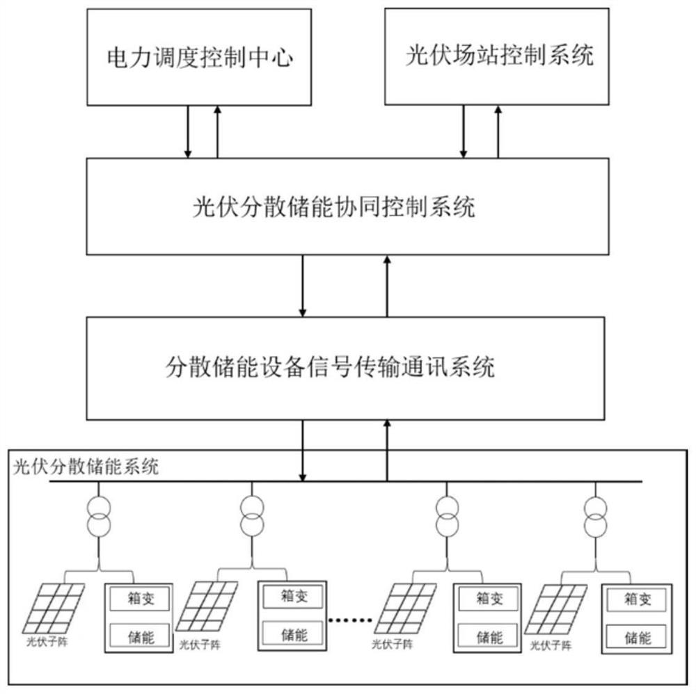
[0041] like figure 1 As shown in the figure, a distributed energy storage system based on a photovoltaic field station, the distributed energy storage system is respectively connected with the power dispatching control center and the photovoltaic field station control system, and the distributed energy storage system includes the photovoltaic field area distributed energy storage sub-systems connected in sequence. The system, the signal transmi...


PUM


Abstract

The invention relates to a distributed energy storage system based on a photovoltaic station, and the system is connected with a power dispatching control center and a photovoltaic station control system. The distributed energy storage system comprises a photovoltaic field area distributed energy storage subsystem, a distributed energy storage equipment signal transmission communication subsystem and a photovoltaic distributed energy storage cooperative control subsystem which are connected in sequence, wherein the photovoltaic distributed energy storage cooperative control subsystem is respectively connected with a power dispatching control center and a photovoltaic field station control system. Compared with the prior art, the method has the advantages that the profitability of the photovoltaic power station and the overall benefit of dispersed energy storage are improved, and the like.

Description

technical field [0001] The present invention relates to a distributed energy storage system, in particular to a distributed energy storage system based on photovoltaic fields. Background technique [0002] Against the background of increasingly depleting fossil energy and global climate change caused by greenhouse gases, photovoltaic power generation systems have developed rapidly in recent years due to their clean, efficient and renewable conditions. With the rapid development of photovoltaics and other clean energy sources, the power grid consumption capacity and power system adjustment resources that are suitable for the development scale are gradually facing challenges. High-quality development of energy. In order to achieve the goals of carbon peaking by 2030 and carbon neutrality by 2060 as scheduled, the country will build a new power system with new energy as the main body. Photovoltaic plus appropriate amount of energy storage can solve the problem of photovoltaic ...

Claims


Application Information

Patent Timeline
Patent Type & Authority Applications(China)
IPC IPC(8): H02J3/38H02J3/32H02J3/24H02J3/06H02J13/00
CPCH02J3/381H02J3/32H02J3/24H02J3/06H02J13/00017H02J2300/24
Inventor 邢连中刘思广王文庆姚峻祝建飞林权薛明华王日成张翼冯波
Owner 国家电投集团江苏电力有限公司
Why Eureka
Try Eureka