
Gate lifting device applied to water conservancy

A gate, water conservancy technology, applied in the field of water conservancy gate lifting devices, can solve problems such as easy corrosion and damage

Pending Publication Date: 2022-08-02
蒙城县水利局建筑工程队
View PDF1 Cites 0 Cited by
  • Summary
  • Abstract
  • Description
  • Claims
  • Application Information

AI Technical Summary

Problems solved by technology

[0004] In view of the above-mentioned related technologies, the inventor believes that the second driving part of the water conservancy gate is fixed on the gate plate, and the third driving part is fixed on the installation frame, that is, the lifting device of the water conservancy gate is exposed on the outside of the water conservancy gate. Exposure to wind and sun is prone to corrosion and damage

Method used


Image

  • Gate lifting device applied to water conservancy
  • Gate lifting device applied to water conservancy
  • Gate lifting device applied to water conservancy

Examples


Embodiment Construction

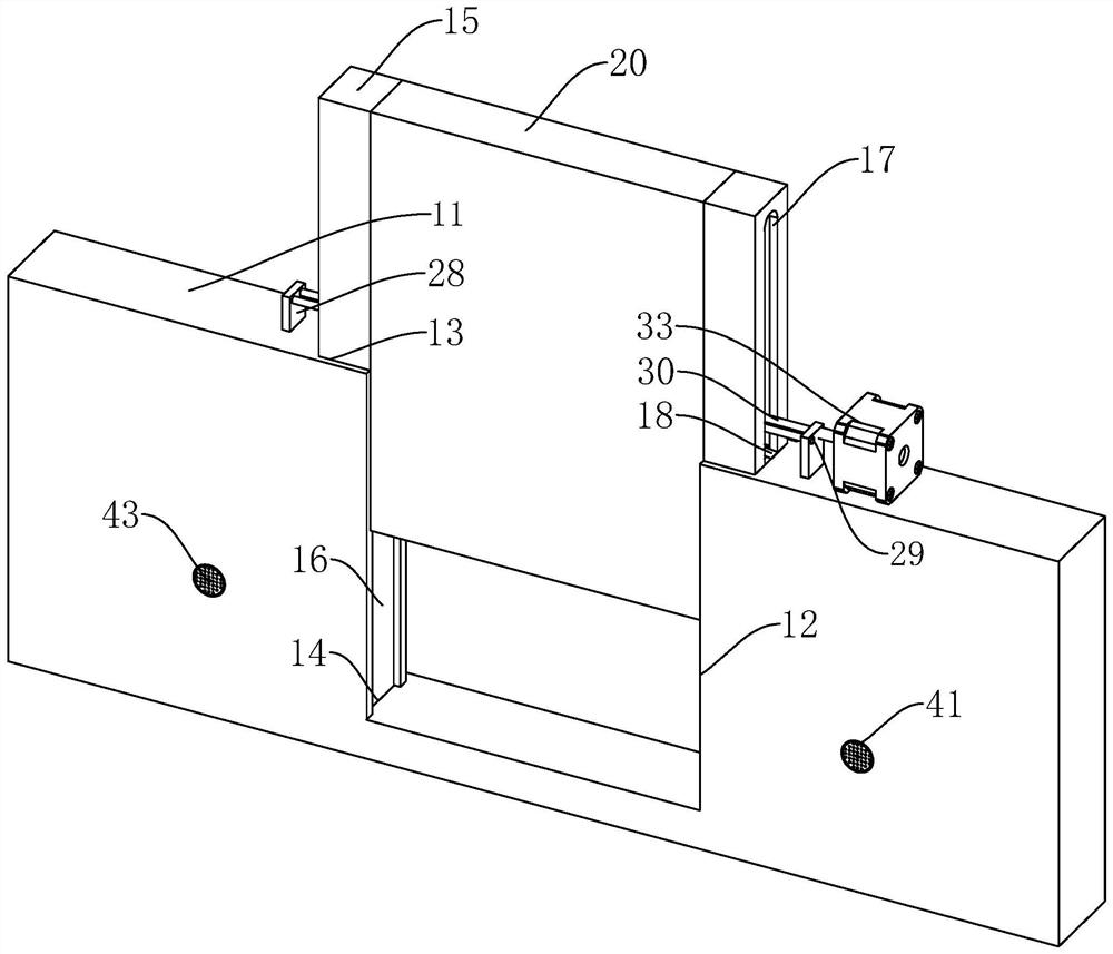
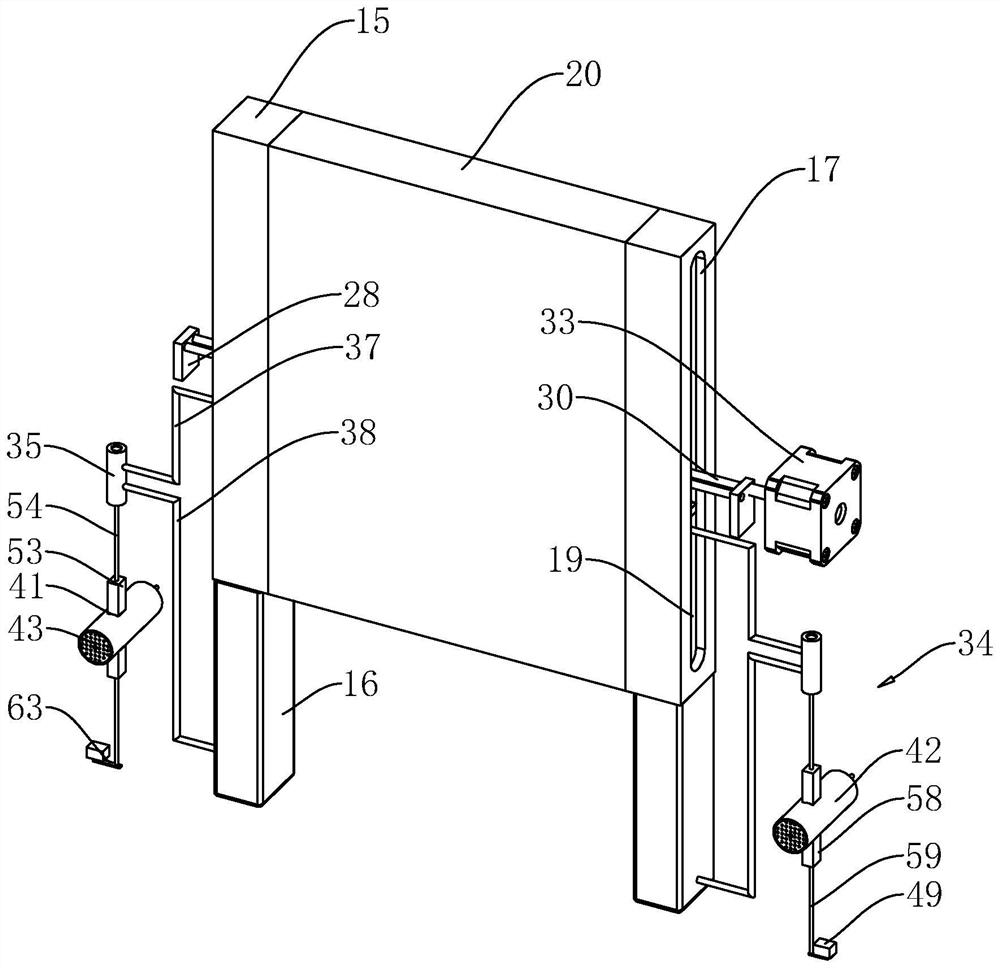
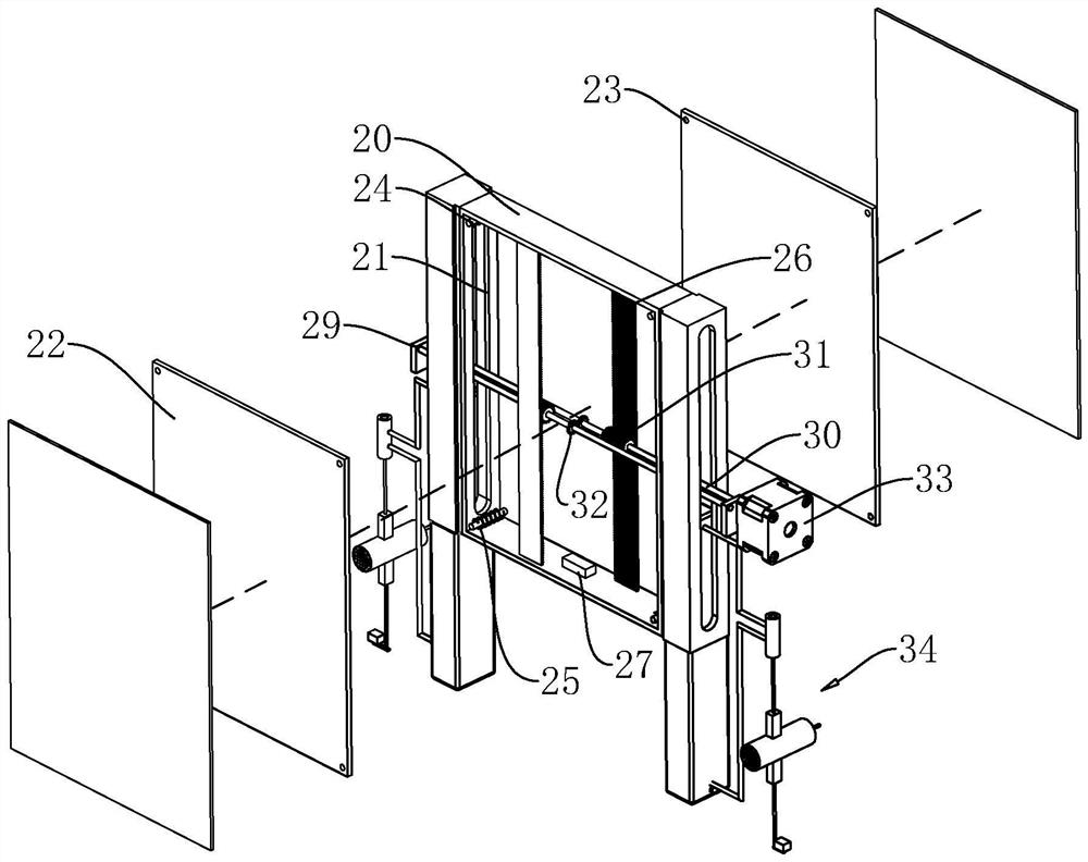
[0035] Attached to the following Figure 1-5 This application will be described in further detail.

[0036] The embodiment of the present application discloses a gate lifting device applied to water conservancy. refer to figure 1 and figure 2 As shown in the figure, the gate lifting device applied to water conservancy includes a baffle plate 11. The baffle plate 11 is located on its top surface and has an enclosure groove 12 running through its front and rear sides. The inner side walls are provided with slide rail grooves 13 along the height direction of the enclosure plate 11 . The inner bottom surface of the enclosure groove 12 is provided with a collection groove 14 . The collection grooves 14 are provided with two groups along the length direction of the enclosure plate 11 . The collection groove 14 is a groove structure with a rectangular cross section.

[0037] refer to figure 1 and figure 2 As shown, the enclosing plate 11 is installed with a sliding rail squa...


PUM


Abstract

The invention relates to the technical field of water conservancy projects, in particular to a gate lifting device applied to water conservancy, which comprises a fence flat plate and a servo motor mounted on the top surface of the fence flat plate, the fence flat plate is provided with a fence groove, and a gate flat plate is slidably arranged on the fence flat plate through the fence groove. A driving mechanism used for driving the gate flat plate to ascend and descend is arranged in the gate flat plate and comprises two sets of driving straight rods rotationally installed on the top face of the fence flat plate, a plurality of lifting gears fixed to the peripheral sides of the driving straight rods and synchronous gears fixed to the peripheral sides of the driving straight rods, and two sets of lifting flat plates are arranged in the gate flat plate in a sliding mode. A lifting rack is fixed to the side face of the lifting flat plate for meshing, the two synchronous gears are meshed, and a sliding mechanism used for driving the lifting rack to move is arranged in the gate flat plate. The lifting device has the effect that the lifting device of the water conservancy gate is exposed to the outer side of the water conservancy gate and is extremely prone to corrosion and damage after long-time wind and sun exposure.

Description

technical field [0001] The present application relates to the technical field of water conservancy engineering, and in particular, to a gate lifting device applied to water conservancy. Background technique [0002] The gate is a control facility used to close and open the drainage channel. It is an important part of the building of the water conservancy project. It can be used to intercept the water flow, control the water level, adjust the flow, and discharge sediment and floating objects. In the construction of water conservancy projects, workers often need to use water conservancy gates to control the water storage capacity of rivers and reservoirs. [0003] For example, the Chinese utility model patent with the authorization announcement number CN214737860U discloses a water conservancy gate. The water conservancy gate includes a mounting frame and a gate plate slidably arranged on the mounting frame. A closing plate that closes the through hole is slidably arranged in...

Claims


Application Information

Patent Timeline
IPC IPC(8): E02B7/26E02B7/36
CPCE02B7/26E02B7/36Y02E10/20
Inventor 李鑫邹亮马大龙
Owner 蒙城县水利局建筑工程队
Learn More