
Flow guide disc installation method and installation device

An installation method and a technology for installation devices, which are applied in the direction of machines/engines, manufacturing tools, blade support elements, etc., can solve the problems of low installation quality and installation efficiency of the deflector plate, and the inability to achieve precise control of the installation size, etc., to ensure Accuracy, guaranteed installation quality, and improved installation quality and efficiency

Pending Publication Date: 2022-08-02
CHINA HANGFA SOUTH IND CO LTD
View PDF8 Cites 0 Cited by
  • Summary
  • Abstract
  • Description
  • Claims
  • Application Information

AI Technical Summary

Problems solved by technology

[0003] The invention provides a method and device for installing a deflector to solve the problem of the need to use a large torque wrench to apply torque to the compression nut to tighten the deflector during the installation process of the existing aeroengine gas turbine rotor, and to tighten the deflector at the same time. Decomposing the deflector to adjust the amount of compression, resulting in low installation quality and efficiency of the deflector, and the technical problem that precise control of the installation size cannot be achieved

Method used


Image

  • Flow guide disc installation method and installation device
  • Flow guide disc installation method and installation device
  • Flow guide disc installation method and installation device

Examples


Embodiment Construction

[0030] The embodiments of the present invention will be described in detail below with reference to the accompanying drawings, but the present invention can be implemented in many different ways as defined and covered below.

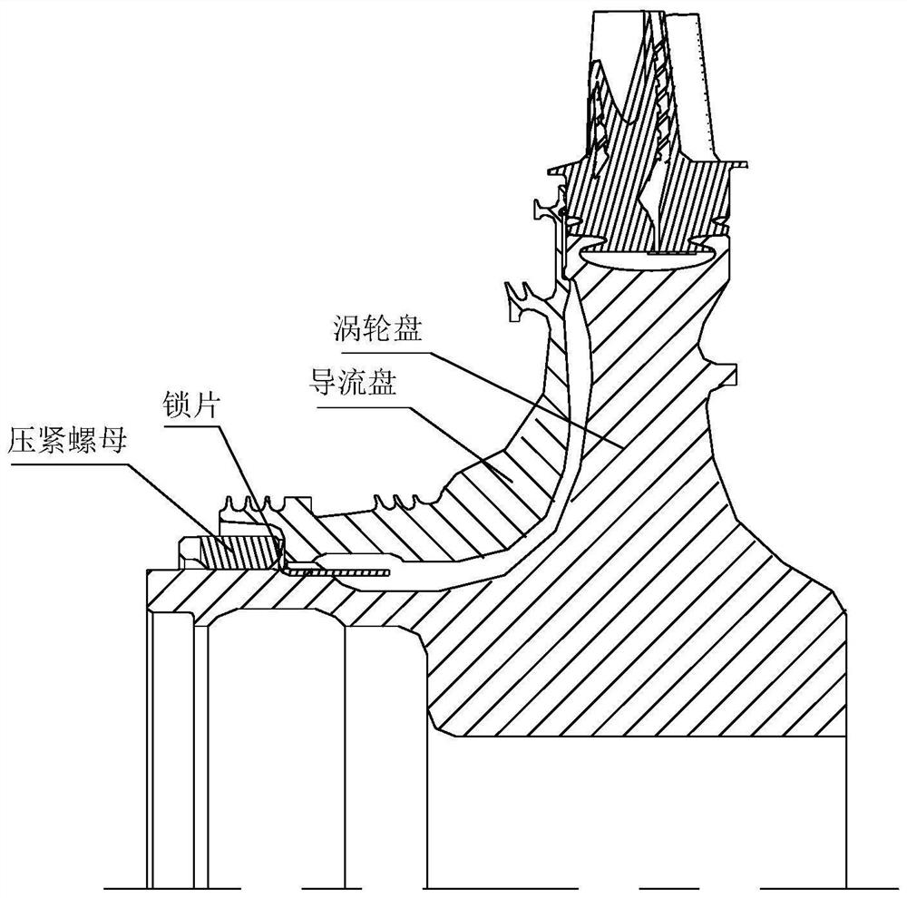
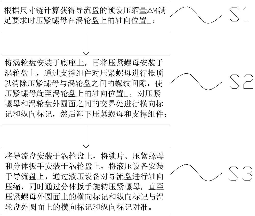
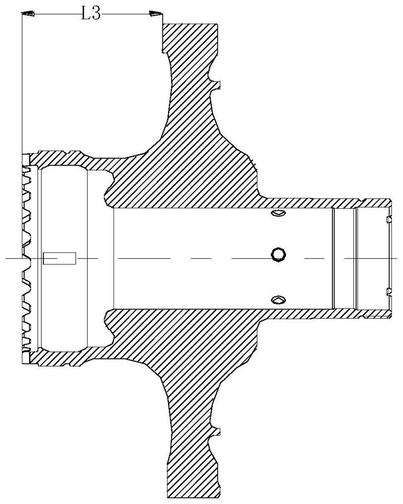
[0031] figure 1 It is a schematic diagram of the structure of the aero-engine gas turbine rotor; figure 2 It is a block diagram of the steps of the installation method of the guide plate according to the preferred embodiment of the present invention; image 3 It is a schematic diagram of the structure of the turbine disk in the rotor of the aero-engine gas turbine; Figure 4 It is a schematic diagram of the structure of the guide plate in the rotor of the aero-engine gas turbine; Figure 5 It is a schematic diagram of the structure of the connection between the guide plate and the turbine disk in the rotor of the aero-engine gas turbine; Image 6 It is a schematic structural diagram of the guide plate device according to the preferred embodiment of t...


PUM


Abstract

The invention discloses a flow guide disc installation method. The method comprises the steps that firstly, the axial distance L between the upper end face of a compression nut and the tooth top face of the upper end of a turbine disc is obtained through size chain calculation when the compression amount of a flow guide disc reaches the preset compression amount M; then, under the condition that the flow guide disc is not installed, the compression nut is made to move by the axial distance L relative to the turbine disc, and transverse marking and longitudinal marking are conducted on the junction between the compression nut and the outer circle face of the turbine disc; the supporting assembly abuts against the pressing nut so that a thread gap between the pressing nut and the turbine disc can be eliminated. Finally, the flow guide disc is axially compressed through hydraulic equipment, meanwhile, the compression nut is rotated through the split wrench, compared with the prior art, a high-torque wrench does not need to be used for screwing the compression nut, and damage to compression nut threads, turbine disc threads and turbine disc end teeth caused by thread friction force is avoided; and the compression amount can be adjusted without repeatedly disassembling and assembling the flow guide disc, so that the mounting quality and efficiency are obviously improved.

Description

technical field [0001] The present invention relates to the technical field of engine parts assembly, in particular, to a method for installing a deflector. In addition, the present invention also relates to a guide plate installation device using the above guide plate installation method. Background technique [0002] Aero-engine gas turbine rotors have high requirements for installation accuracy, and it is necessary to precisely control the installation size between the turbine disk and the guide disk. The existing installation structure between the turbine disk and the guide disk is an interference fit, and the interference If the amount is large, the guide plate is usually installed by heating, and the guide plate is axially tightened in the direction of applying torque to the compression nut with a large torque wrench. Because the compression amount of the guide plate △M is strictly controlled Therefore, it is necessary to repeatedly disassemble the guide plate to adju...

Claims


Application Information

Patent Timeline
Patent Type & Authority Applications(China)
IPC IPC(8): F01D5/30F01D5/32F01D25/00B25B27/14
CPCF01D5/3007F01D5/3053F01D5/32F01D25/00B25B27/14Y02E10/20
Inventor 曹立廷赵媛媛邵雅君高航熊炳文
Owner CHINA HANGFA SOUTH IND CO LTD
Learn More