
Upright rear-drive tight coupling type exhaust manifold

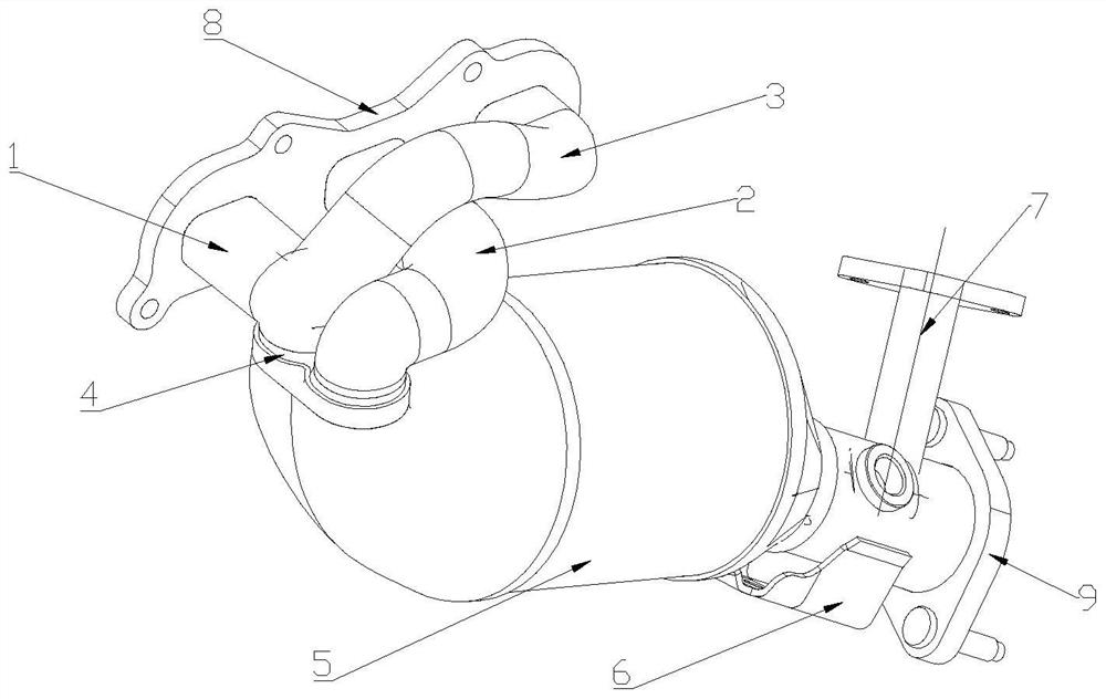
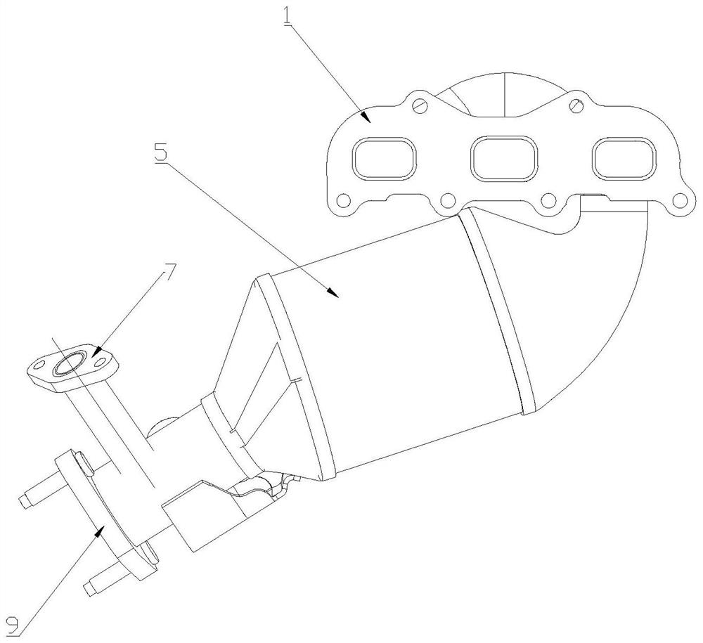
An exhaust manifold and integrated exhaust manifold technology, applied in exhaust devices, air quality improvement, combustion engines, etc., can solve the problems of reducing engine torque and power, affecting the smooth discharge of exhaust gas, etc., to improve power and torque , The effect of facilitating the layout of the whole machine and preventing airflow disturbance

Pending Publication Date: 2022-08-02
HARBIN DONGAN AUTO ENGINE
View PDF0 Cites 0 Cited by
  • Summary
  • Abstract
  • Description
  • Claims
  • Application Information

AI Technical Summary

Problems solved by technology

In addition, the traditional intake pipe form tends to form turbulent flow near the cylinder head outlet, affecting the smooth discharge of exhaust gas, thereby reducing the torque and power of the engine

Method used


Image

  • Upright rear-drive tight coupling type exhaust manifold
  • Upright rear-drive tight coupling type exhaust manifold
  • Upright rear-drive tight coupling type exhaust manifold

Examples


Embodiment Construction

[0013] In order to better understand the purpose, structure and function of the present invention, the present invention will be described in further detail below with reference to the accompanying drawings.

[0014] The exhaust manifold is matched with an upright rear-drive four-cylinder four-stroke engine. The working sequence of one-three-four-two cylinders makes the exhaust strokes of the two and three cylinders not adjacent, thus ensuring that the exhaust gases of the two and three cylinders converge. Without interfering with each other, there is sufficient exhaust time, such as image 3 As shown in the figure, the exhaust manifolds of the second and third cylinders are integrated into the cylinder head. Under the premise of effectively avoiding the mutual interference of the exhaust air flow, the high temperature of the exhaust manifold can quickly heat the antifreeze when the car is cold, which greatly reduces the hot car. time and improve thermal efficiency.

[0015] ...


PUM


Abstract

The invention discloses a vertical rear-drive tight coupling type exhaust manifold, and belongs to the technical field of automobile engine exhaust systems. Space occupation of an exhaust system can be reduced, airflow turbulence can be prevented, engine power and torque are effectively improved, and the purposes of energy conservation and emission reduction are achieved. A first cylinder exhaust manifold, a second and third cylinder integrated exhaust manifold and a fourth cylinder exhaust manifold are sequentially communicated with an air inlet of the front flange, the exhaust end of the first cylinder exhaust manifold and the exhaust end of the fourth cylinder exhaust manifold are gathered at the position of the first and fourth cylinder integrated exhaust manifold, and the first and fourth cylinder integrated exhaust manifold and the second and third cylinder integrated exhaust manifold are communicated with an inlet of a catalyst carrier. The outlet of the catalyst carrier is communicated with the exhaust hole of the rear flange. Through compact arrangement, the exhaust manifold is compressed in width and height, space occupation of an exhaust system is reduced, whole machine arrangement is facilitated, various cabin arrangement requirements are met, meanwhile, airflow turbulence can be prevented, engine power and torque are effectively improved, and the purposes of energy conservation and emission reduction are achieved.

Description

technical field [0001] The invention belongs to the technical field of automobile engine exhaust systems, in particular to an upright rear-drive tightly coupled exhaust manifold. Background technique [0002] With the continuous development of the automotive industry, the engine compartment is more compact in design, requiring the engine to be arranged in a narrow cabin space and avoiding corresponding parts, and at the same time requiring the engine to have higher working efficiency. In addition, the traditional intake pipe form is prone to turbulent flow near the cylinder head outlet, which affects the smooth discharge of exhaust gas, thereby reducing the torque and power of the engine. [0003] Therefore, starting from the engine body, designing a tightly coupled exhaust system structure to meet performance and emission requirements is a technical problem to be solved urgently by those skilled in the art. SUMMARY OF THE INVENTION [0004] In order to solve the problems...

Claims


Application Information

Patent Timeline
IPC IPC(8): F01N13/10
CPCF01N13/107Y02T10/12
Inventor 王刚滕红王德春刘侠庞玉超夏特孙晓鹏杨文盼郭家玮
Owner HARBIN DONGAN AUTO ENGINE
Learn More