
Solar power generation system

A technology of solar power generation panels and power generation systems, which is applied in the field of solar power generation systems, can solve problems such as the reduction of power generation efficiency, and achieve the effects of improving power generation efficiency, reducing the number of installations, and promoting reduction

Pending Publication Date: 2022-08-02
NICHIMO CORP +2
View PDF3 Cites 0 Cited by
  • Summary
  • Abstract
  • Description
  • Claims
  • Application Information

AI Technical Summary

Problems solved by technology

[0004] Such a solar power generation system composed of a large number of solar power generation panels is installed on a large outdoor site, and therefore requires a huge amount of work for maintenance, that is, for example, it is necessary to suppress the occurrence of growth of debris from the site surface under the solar power generation panels. Grass operation, etc. so as not to reduce power generation efficiency

Method used


Image

  • Solar power generation system
  • Solar power generation system
  • Solar power generation system

Examples


no. 1 approach

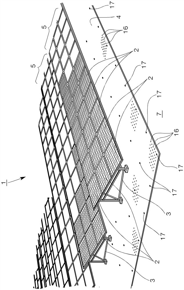
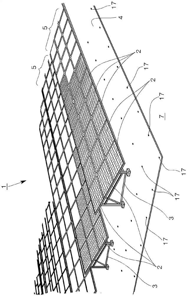
[0057] figure 1 It is a perspective view which shows the outline of the solar power generation system which concerns on embodiment of this invention.

[0058] The solar power generation system 1 of the present embodiment includes a solar power generation panel 2 , a mount 3 , and a reflector 4 as main structures.

[0059] The solar power generation panel 2 is configured by integrating and modularizing a plurality of solar battery cells. In this embodiment, the solar battery cells are provided on both the front and rear surfaces, and the power generation surfaces are double-sided. Incident type solar power generation panel.

[0060] like figure 1 As shown, a plurality of solar power generation panels 2 are arranged vertically and horizontally, and are connected to grow in a horizontal direction, and are mounted on a rack 3 to be described later to constitute a solar cell array 5 formed in the depth direction. It is arranged on a desired wide field in multiple rows. This sol...


PUM

PropertyMeasurementUnit
thicknessaaaaaaaaaa
thicknessaaaaaaaaaa
densityaaaaaaaaaa

Abstract

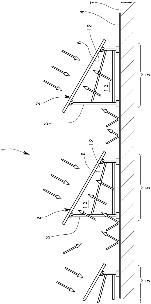
The purpose of the present invention is to improve power generation efficiency, to reduce the floor area, and to increase the amount of power generation while reducing the costs for construction, maintenance, and the like. A solar power generation system is provided with a plurality of solar power generation panels (2) provided such that an upper power generation surface (6) is inclined toward the incident direction of sunlight by means of a gantry (3). The solar power generation panel (2) is formed from a double-sided incident solar power generation panel provided with power generation surfaces (6, 12) on both upper and lower surfaces, a light passage space (13) is provided below the power generation surface (12) on the lower surface, and a reflector (4) is laid so as to cover the lower part of the double-sided incident solar power generation panel (2) and a ground surface (7) around the double-sided incident solar power generation panel (2). The front surface side of the reflector (4), which faces the lower power generation surface (12), is provided with a reflective layer (14) that is formed of a thin sheet material having a high light reflectance, said thin sheet material reflecting direct light and scattered light of sunlight toward the lower power generation surface (12). The back surface side of the reflector (4), which faces the ground surface (7) and is in contact with the ground surface (7), is provided with a grass-proof layer (15) formed by a grass-proof sheet material, and the reflecting layer (14) and the grass-proof layer (15) are integrally formed in a laminated manner.

Description

technical field [0001] The present invention relates to a solar power generation system. Background technique [0002] Conventionally, as a solar power generation system, there is a system called a mega-watt-class solar power station (Mega Solar) in which a large number of solar power generation panels are arranged on the ground to generate power on a large scale. [0003] As shown in Patent Documents 1 and 2 below, this megawatt-class solar power plant has a large number of solar power generation panels installed on a wide site, and each of the solar power generation panels is arranged via a rack in a state of being inclined at a predetermined angle. [0004] Such a solar power generation system consisting of a large number of solar power generation panels is installed on a large outdoor site, and therefore requires a large amount of work for maintenance, that is, for example, it is necessary to suppress the occurrence of growth of impurities from the surface of the site un...

Claims


Application Information

Patent Timeline
Patent Type & Authority Applications(China)
IPC IPC(8): H02S40/22H02S20/10
CPCH02S40/22H02S20/30C08L23/06C08L2207/066C08L2205/025C08K2003/2241C08L2203/20C08K3/22C08K5/3435C08K3/04H02S20/10Y02E10/50Y02E10/52C08L23/04C08K3/013B32B27/32B32B27/327B32B27/18B32B27/08B32B15/085B32B2307/416B32B2323/046A01G13/0256
Inventor 日浦一朗鲤内隆弘中井贵晓大西康平日向雄纪
Owner NICHIMO CORP
Learn More