Double-end-face grinding machine

A double-end surface grinding machine and grinding disc technology, which can be used in grinding machines, grinding machine bodies, grinding machine parts, etc., can solve problems such as waste of human resources and low efficiency.

Active Publication Date: 2022-08-05
宁波邦一机械科技有限公司
View PDF14 Cites 1 Cited by
  • Summary
  • Abstract
  • Description
  • Claims
  • Application Information

AI Technical Summary

Problems solved by technology

[0004] In the existing magnetic steel double-sided grinding processing equipment, the processing of magnetic steel usually requires a special fixture for manual clamping, and then put it in the grinding channel between the two grinding discs for double-sided grinding of the magnetic steel , After one workpiece is polished, it is unloaded, and then the next workpiece is clamped and polished. This processing method requires special workers for clamping and unloading, resulting in waste of human resources and low efficiency.

Method used


Image

  • Double-end-face grinding machine
  • Double-end-face grinding machine
  • Double-end-face grinding machine

Examples


Embodiment Construction

[0026] In order to make the above-mentioned objects, features and advantages of the present invention more clearly understood, specific embodiments of the present invention will be described in detail below with reference to the accompanying drawings.

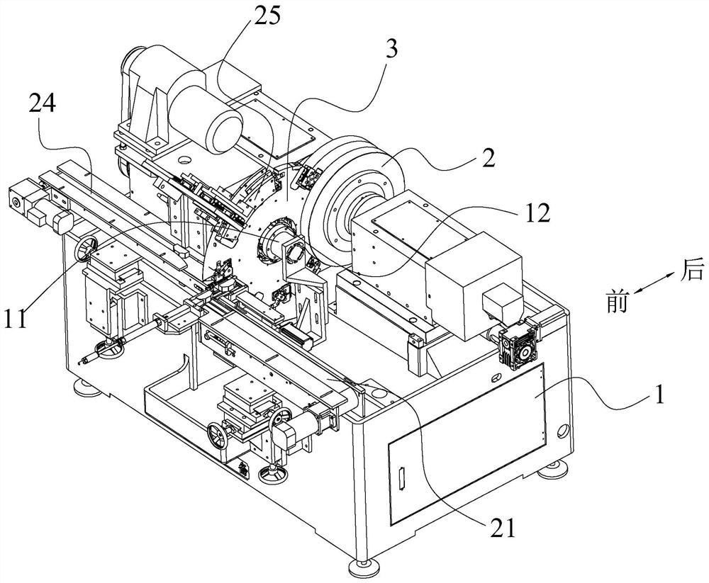
[0027] In the description of the present invention, it should be noted that the orientations or positional relationships indicated by the terms "outer end", "inner end", "front side", "rear side", "side wall", etc. are based on those shown in the accompanying drawings The orientation or positional relationship is only for the convenience of describing the present invention and simplifying the description, rather than indicating or implying that the indicated device or element must have a specific orientation, be constructed and operated in a specific orientation, and therefore should not be construed as a limitation of the present invention .

[0028] In the description of the present invention, it should be noted that, unless ...


PUM


Abstract

The invention provides a double-end-face grinding machine which comprises a machine base. Two grinding discs, a feeding assembly, a feeding rotary disc and a motor for driving the feeding rotary disc to rotate are installed on the machine base. A plurality of mounting grooves are formed in the circumferential outer wall of the feeding rotary disc in an inward concave mode, and pressing assemblies are assembled on the sides, in the width direction, of the interiors of the mounting grooves and can stretch out and draw back in the width direction of the mounting grooves; a workpiece positioning channel with the adjustable width is formed between the pressing face of the pressing assembly and the other side of the installation groove in the width direction. The feeding rotary disc is further connected with a driving assembly, and when the motor drives the feeding rotary disc to rotate to different set positions in the circumferential direction, the driving assembly is used for driving the pressing assembly to stretch out or retract, so that the workpieces are clamped or loosened. According to the double-end-face grinding machine, the grinding channel used for conveying workpieces on the feeding mechanism to the position between the grinding discs one by one is additionally arranged between the two grinding discs, and clamping of the workpieces is stable and efficient.

Description

technical field [0001] The invention relates to the technical field of grinding equipment, in particular to a double-end grinding machine. Background technique [0002] Magnetic steel is mainly used in various sensors, instruments, electronics, electromechanical, medical, teaching, automobile, aviation, military technology and other fields. According to the different metal composition of the magnetic steel, its magnetic properties will be different, and thus the uses will be different. [0003] At present, the magnetic steel will be manufactured by powder metallurgy, and at the same time, it will be ground by a grinding device after the production is completed; grinding is the most common and widely used processing method in all mechanical processing. The edges need to be ground into the desired shape, such as chamfering, rounding, or grinding of irregular planes on the edges of metal parts. [0004] In the existing magnetic steel double-sided grinding processing equipment,...

Claims


Application Information

Patent Timeline
Patent Type & Authority Applications(China)
IPC IPC(8): B24B7/17B24B41/00B24B27/00B24B41/02B24B41/06
CPCB24B7/17B24B41/005B24B27/0076B24B41/02B24B41/06Y02P70/10
Inventor 陈达幸
Owner 宁波邦一机械科技有限公司
Why Eureka
Try Eureka