Composite material radome arc flange interface hole machining clamp and machining method

A composite material and radome technology, which is applied in metal processing and other directions, can solve problems such as difficulty in positioning and clamping of workpieces, easy breakage of drill bits, and small top plane, etc., to ensure task progress, wide application range, and strong operability Effect

Pending Publication Date: 2022-08-05
浙江微控智造有限公司 +1
View PDF0 Cites 0 Cited by
  • Summary
  • Abstract
  • Description
  • Claims
  • Application Information

AI Technical Summary

Problems solved by technology

Due to the irregular shape of the radome, under the action of single-sided radial force, the drill bit will produce serious eccentricity and cannot drill into the workpiece, or barely drill into the workpiece but it is difficult to ensure the verticality and roundness requirements of the hole, and the drill bit Easily broken
Drilling from the opposite side, that is, drilling the radome upside down. Due to the small top plane, it is difficult to position and clamp the workpiece, and it is impossible to ensure that the processed hole is perpendicular to the bottom surface.
Although the processing of electric hand drill is flexible and convenient, its disadvantages are similar to those of bench drill processing. No matter drilling from the front or back of the flange, it is difficult to guarantee the quality of the hole, and the processing stability of electric hand drill is worse than that of bench drill. , we propose a composite material radome arc-shaped flange interface hole processing fixture and processing method to solve the problems raised in the above-mentioned background technology

Method used


Image

  • Composite material radome arc flange interface hole machining clamp and machining method
  • Composite material radome arc flange interface hole machining clamp and machining method
  • Composite material radome arc flange interface hole machining clamp and machining method

Examples


Embodiment Construction

[0032] The following will clearly and completely describe the technical solutions in the embodiments of the present invention. Obviously, the described embodiments are only a part of the embodiments of the present invention, rather than all the embodiments. Based on the embodiments of the present invention, all other embodiments obtained by those of ordinary skill in the art without creative efforts shall fall within the protection scope of the present invention.

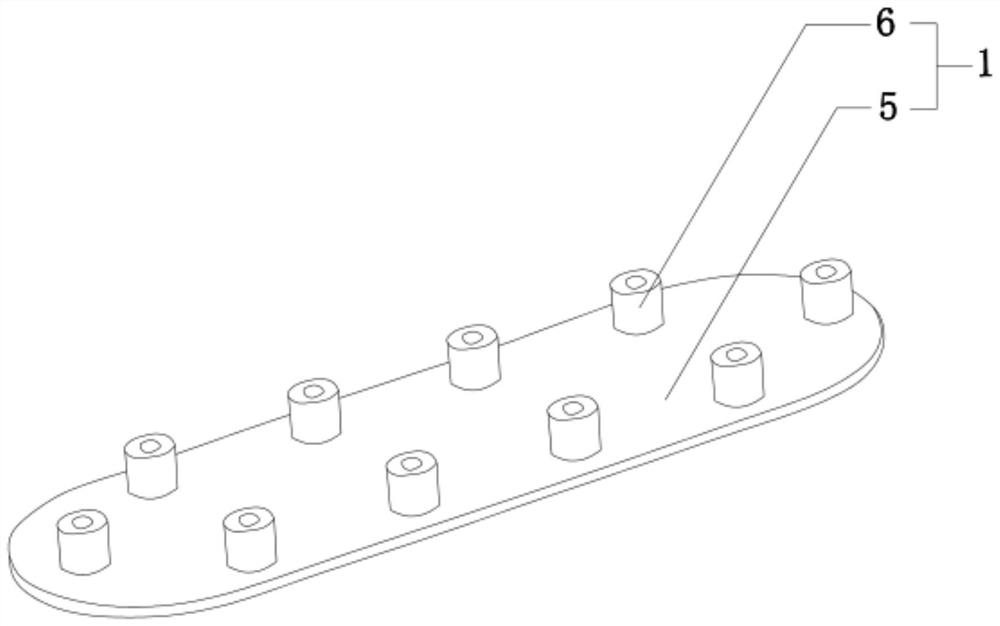
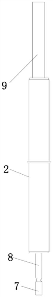
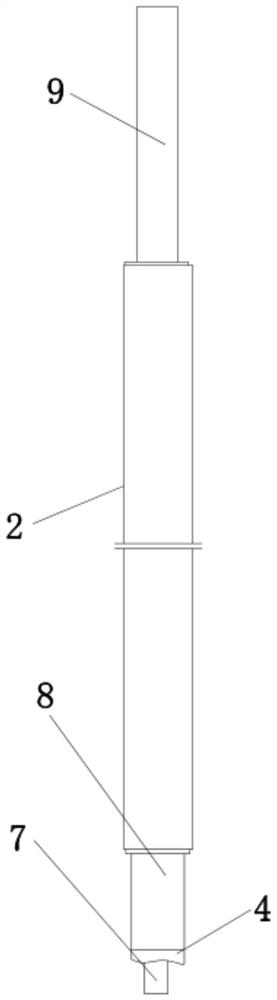
[0033] like Figure 1 to Figure 6 As shown, a composite material radome arc flange interface hole processing fixture in this embodiment includes a drilling fixture 1 and a special countersinking tool 2 .

[0034]The drilling jig 1 is composed of a positioning plate 5 that is used to be placed on the reverse side of the radome flange 11 to limit the position and a drill sleeve 6 that is used for positioning and limiting the hole position when drilling. , the radome flange 11 at the bottom of the radome 3 has an edge...


PUM


Abstract

The invention discloses a composite radome arc-shaped flange interface hole machining clamp and method. The composite radome arc-shaped flange interface hole machining clamp comprises a drilling clamp and a special countersinking tool. The drilling clamp is composed of a positioning plate used for positioning during drilling and a drilling sleeve used for position guiding in the drilling process, the thickness of the positioning plate is 3 mm, an antenna housing is arranged on the top of the positioning plate, and the appearance of the positioning plate is matched with an oval pit in the bottom of the antenna housing. A drilled hole is positioned and guided through the drilling clamp, accurate drilling is conducted on an arc-shaped flange interface of the radome according to the required position, then the guide part of the special countersinking tool is inserted into the drilled hole, the countersinking tool guide column part is used for limiting and guiding, and the countersinking tool body blade part is used for countersinking. The machined hole is accurate in position and qualified in size, a special drilling tool does not need to be customized, the cost is saved, meanwhile, the task progress can be better guaranteed, and the method is easy to master, high in operability and wide in application range.

Description

technical field [0001] The invention relates to the technical field of radome arc-shaped flange interface hole processing, in particular to a composite material radome arc-shaped flange interface hole processing fixture and a processing method. Background technique [0002] As a functional bearing and protection structure of the antenna body, the radome mainly plays the role of bearing the antenna body and protecting the internal antenna from the external environment, thereby improving the reliability of the antenna operation and ensuring the antenna to work all day long. Therefore, the radome not only needs to have certain structural strength and rigidity, but also needs to have good electrical properties. [0003] The FRP radome is made of high-strength glass fiber reinforced composite material, which has a very small dielectric constant (ε) and dielectric loss tangent (tanδ), as well as light weight, high specific strength, corrosion resistance, fatigue resistance, It ha...

Claims


Application Information

Patent Timeline
Patent Type & Authority Applications(China)
IPC IPC(8): B26D7/01B26F1/16
CPCB26D7/01B26F1/16
Inventor 郑立新徐英芳王雪峰
Owner 浙江微控智造有限公司
Why Eureka
Try Eureka