
Sealing device for ultra-high-speed turbine rotor

A turbine rotor and sealing device technology, applied in gas turbine devices, jet propulsion devices, high-efficiency propulsion technology, etc., can solve the problems of cluttered acoustic emission signals, difficult noise reduction and instability of acoustic emission signals, and achieve compact structure and reduce contact. The effect of excessive stiffness and small size

Active Publication Date: 2022-08-05
浙大宁波理工学院
View PDF7 Cites 0 Cited by
  • Summary
  • Abstract
  • Description
  • Claims
  • Application Information

AI Technical Summary

Problems solved by technology

[0004] Aiming at the deficiencies and defects of the existing technology, a method is provided that can effectively solve the problems that the acoustic emission signal generated by the mechanical seal is chaotic, unstable, and contains a lot of noise during the start-stop phase, and can effectively solve the problem that the acoustic emission signal of the mechanical seal is difficult. The bottleneck of noise reduction

Method used


Image

  • Sealing device for ultra-high-speed turbine rotor
  • Sealing device for ultra-high-speed turbine rotor
  • Sealing device for ultra-high-speed turbine rotor

Examples


Embodiment Construction

[0023] The technical solutions in the embodiments of the present application will be clearly and completely described below with reference to the drawings in the present embodiments. Obviously, the described embodiments are only a part of the embodiments of the present invention, but not all of the embodiments. Based on the embodiments in this application, all other embodiments obtained by those of ordinary skill in the art without creative work fall within the scope of invention protection.

[0024] It should be understood that although the terms upper, middle, lower, outer, inner, etc. may appear herein to describe various elements, these elements should not be limited by these terms. These terms are only used to distinguish elements from one another for ease of understanding, and are not used to define any directional or sequential limitations.

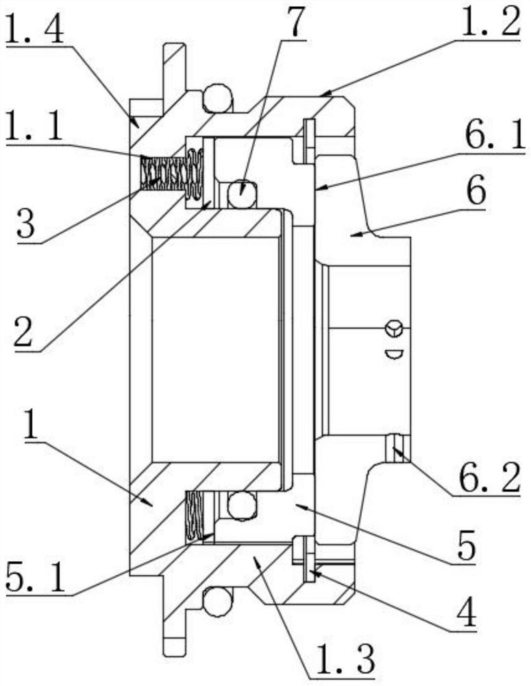
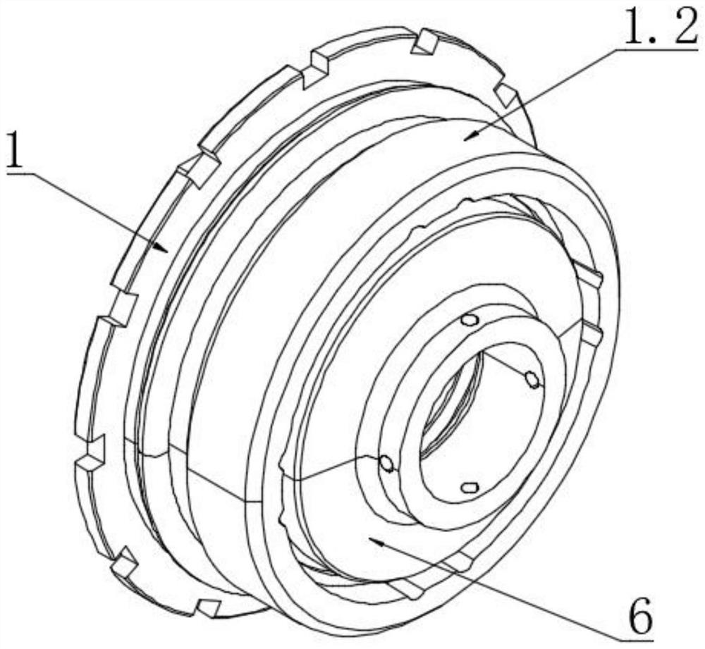
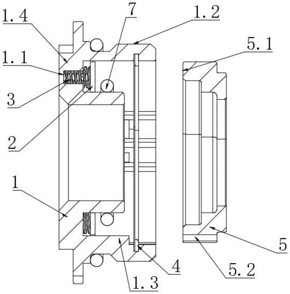
[0025] An embodiment of the present disclosure provides a sealing device for an ultra-high-speed turbine rotor, such as figure 1...


PUM


Abstract

The invention discloses a sealing device for an ultra-high-speed turbine rotor, which comprises a flexible compensation assembly and a rotating assembly, and the rotating assembly and the flexible compensation assembly are coaxially arranged; the flexible compensation assembly comprises a thrust seat, a thrust ring, a plurality of springs and a sealing compensation ring; the rotating assembly comprises a sealing rotating ring, and the sealing rotating ring and a turbine rotor bearing bush are integrated. The compensation thrust seat comprises an annular mounting groove, and the springs are arranged in the annular mounting groove at intervals; the tail end of the spring abuts against the thrust ring. The sealing compensation ring comprises a first end face facing the thrust ring, and the first end face makes contact with the thrust ring. The sealing rotating ring comprises a second end face facing the sealing compensation ring, and the second end face abuts against the sealing compensation ring and makes flexible contact with the sealing compensation ring. Compact installation can be achieved, related sealing parts are in flexible sealing contact, automatic regulation and compensation can be achieved, and high-reliability and zero-leakage operation is achieved.

Description

technical field [0001] The invention relates to the technical field of aerospace ultra-high-speed sealing, in particular to a sealing structure that can be used for ultra-high-speed (≥60000 r / min) turbine rotor power propulsion devices. Background technique [0002] Hypersonic vehicle is a new type of next-generation aviation / spacecraft powered by air-breathing or combined engine and flying at hypersonic speed (Ma>5). Hypersonic aircraft can be used in many fields such as military, civil aviation, and round-trip between space and earth, representing an important development direction in the field of aircraft in the future. When flying in the atmosphere, hypersonic vehicles usually use a combined cycle power system dominated by scramjets, such as a turbine-based combined cycle propulsion system, so as to take advantage of the high specific impulse of air-breathing engines as much as possible. [0003] But the problem is that the above technology has at least the following...

Claims


Application Information

Patent Timeline
IPC IPC(8): F01D11/00F02C7/28
CPCF01D11/003F01D11/00F02C7/28Y02T50/60Y02E10/20
Inventor 陆俊杰张博劼方照东张炜
Owner 浙大宁波理工学院
Learn More